2-21
345 Conquest
Section 2 • General Information
Section 2 • General Information
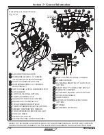
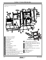
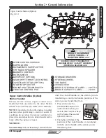
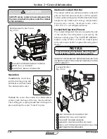
Upper Control Station (Option)
Fig. 2.21.1
UPPER CONTROL CONSOLE
CUPHOLDERS
RAYMARINE CHART/PLOTTER
VHF RADIO SPEAKER
MAGNETIC COMPASS
HORN SWITCH
AUTOPILOT (OPTION)
GEAR SHIFT/THROTTLE CONTROL
JOYSTICK PILOTING (OPTION)
START/STOP SWITCH
ENGINE SHUT DOWN SWITCH
TRIM TAB CONTROL PAD
1
2
3
4
5
6
7
STORAGE DRAWERS
STEERING WHEEL
VHF RADIO
VESSEL VIEW
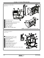
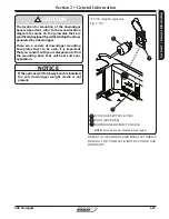
BRIDGE CLEARANCE LABEL ......2027713
BRIDGE CAPACITY LABEL ...........221911
8
9
10
11
12
13
Upper Control Station (Option)
BRIDGE CAPACITY INFORMATION
MAXIMUM WEIGHT CAPACITY UNDERWAY
(PERSONS & GEAR) 450 LBS.
!
CAUTION
BRIDGE CLEARANCE
W/OUTRIGGERS = 23’
17
18
14
15
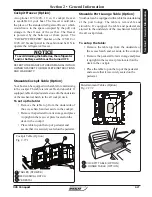
Station transfer allows engine control to be
transferred from one station to the other. Station
transfer can be achieved by either of two methods.
NOTE:
It is preferred to have the engines in neutral
position when performing a station transfer. If
conditions do not allow the remote controls to be
placed in a neutral position, a station transfer can be
made while the engines is in gear.
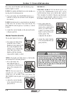
METHOD 1
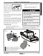
Transfer delay:
This method delays station transfer
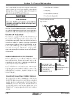
Station Transfer
until the control handles at the station you are
transferring to match the handle positions of the
station you are transferring from.
1. Press and release the
TRANSFER button at the
control station where you
want to take control. A beep
will be heard. The neutral
light will turn on.
2. The lights will blink if the
positions of the control handles are not aligned
with the control handles at the station you are
transferring from.
1
2
3
4
5
6
7
8
9
10
11
13
12
2
14
15
16
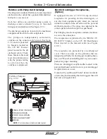
PORT
CENTER
STBD
N
N
SYNC
TRANSFER
1 LEVE
R THROTTLE
ONL
Y
DOCK
PORT
CENTER
STBD
N
N
SYNC
TRANSFER
1 LEVER THROTTL
E
ONLY
DOCK
UPPER TOWER = 17’
16
17
18
Summary of Contents for CONQUEST 345
Page 21: ...xix 345 Conquest THIS PAGE INTENTIONALLY LEFT BLANK...
Page 93: ...2 46 Section 2 General Information 345 Conquest THIS PAGE INTENTIONALLY LEFT BLANK...
Page 150: ...4 16 345 Conquest Section 4 Electrical System Batteries Joystick Steering Option Fig 4 16 1...
Page 152: ...4 18 345 Conquest Section 4 Electrical System DC MDP Joystick Steering Fig 4 18 1...
Page 154: ...4 20 345 Conquest Section 4 Electrical System AC Power 220V 50Hz Fig 4 20 1...
Page 156: ...4 22 345 Conquest Section 4 Electrical System Cabin O H and Accent Lights Fig 4 22 1...
Page 158: ...4 24 345 Conquest Section 4 Electrical System Wipers and Washers Fig 4 24 1...
Page 160: ...4 26 345 Conquest Section 4 Electrical System Waste System Fig 4 26 1...
Page 161: ...4 27 Section 4 Electrical System 345 Conquest Section 4 Electrical System Windlass Fig 4 27 1...
Page 162: ...4 28 345 Conquest Section 4 Electrical System Trim Tabs Fig 4 28 1...
Page 166: ...4 32 345 Conquest Section 4 Electrical System Pumps Sheet 2 Fig 4 32 1...
Page 168: ...4 34 345 Conquest Section 4 Electrical System V Berth Schematic Fig 4 34 1...
Page 170: ...4 36 345 Conquest Section 4 Electrical System Shore Power 230V 50HZ Fig 4 36 1...
Page 172: ...4 38 345 Conquest Section 4 Electrical System Stereo Premium Option Fig 4 38 1...
Page 174: ...4 40 345 Conquest Section 4 Electrical System Heater CO Monitor Fig 4 40 1...
Page 176: ...4 42 345 Conquest Section 4 Electrical System Generator 230V 50Hz Fig 4 42 1...
Page 178: ...4 44 345 Conquest Section 4 Electrical System STBD AC Harness Fig 4 42 1...
Page 180: ...4 46 345 Conquest Section 4 Electrical System STBD DC Harness Fig 4 44 1...
Page 182: ...4 48 345 Conquest Section 4 Electrical System Windlass Harness Fig 4 46 1...
Page 206: ...5 22 Section 5 Care Maintenance 345 Conquest THIS PAGE INTENTIONALLY LEFT BLANK...

