background image

Bot’n Roll ONE A User Assembling Manual

4.3.3. INTEGRATED CIRCUITS PLACEMENT

An integrated circuit is a miniaturized electronic circuit consistng
mainly of semiconductor devices such as transistors. The number of
transistors   on   integrated   circuits   can   vary   from   a   couple   of
transistors to tens of millions of transistors.

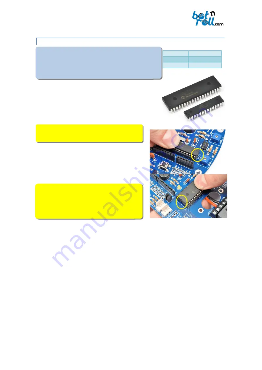
On   the   robot,   two   DIP   format   integrated   circuits   are
used:

PIC18F45K22

: 40 pins processing unit (PIC).

ATmega328

: 28 pins processing unit (Arduino).

NOTE:

  Before   insertng   the   integrated   circuits   ensure

that the Bot'n Roll ONE A is powered OFF.

It   may   be   necessary   to   align   the   pins   of   integrated
circuits   before   insertng  them  on  the   sockets.   Do  this
carefully because the pins are fragile and can break if not
done   properly   or   bended   several   tmes,   becoming
irreparably damaged.

IMPORTANT NOTE

: The integrated circuits have a unique

insertng   positon.   In   one   of   the   edges,   a   cavity
corresponds to the printed mark on the PCB serigraphy.
Insert the ATmega328 on  

U1

  and the PIC18F45K22 on

U2

.

©Copyright 2018, SAR - Soluções de Automação e Robótca, Lda.

38

Fig. 56 Integrated circuits inserton

Descripton Component
U1

ATmega328

U2

PIC18F45K22

Summary of Contents for ONE A

Page 1: ......

Page 2: ...ed with Robotcs 8 1 3 Electronics Defnitons 9 2 Bot n Roll ONE A Components 10 3 Battery 11 3 1 Charging the Battery 11 3 2 Handling the Battery 11 4 Bot n Roll ONE A Assembly 12 4 1 Mechanical Assemb...

Page 3: ...ter 31 4 2 21 Heat sink 32 4 2 22 Voltage Regulators 32 4 2 23 L298 H bridge 33 4 2 24 Infrared Receivers 33 4 2 25 LCD 34 4 2 26 USB Serial Converter Protecton Casing 35 4 3 Wiring and Testng 36 4 3...

Page 4: ...Loading a Program to Bot n Roll ONE A 46 7 Bot n Roll ONE A Hardware Test 47 7 1 L LED 47 7 2 Buzzer 47 7 3 Debug LED 48 7 4 LCD 48 7 5 Push buttons 49 7 6 Battery 49 7 7 Motors 50 7 8 Infrared LED s...

Page 5: ...ws the study of a wide range of concepts in a very practcal perspectve The most experienced will fnd this robotc kit an interestng challenge The Bot n Roll ONE A has two microcontrollers one ATmega328...

Page 6: ...C18F45K22 Obstacle Sensors 2 PIC18F45K22 Buzzer 1 ATmega328 Debugging LED s 2 Motors 2 PIC18F45K22 Nominal Voltage 12V DC Nominal Current 0 58A Rotaton without load 250rpm Nominal Binary 1 16Kg cm Max...

Page 7: ...Control Caster Wheel and robot tlt adjustment ATmega328 Microprocessor ICSP to Program the PIC18F45K22 14 Digital I O s 8 Analog Inputs Line Follower Push Butons Two 12V DC motors and two driving whee...

Page 8: ...w 3rd law a robot must protect its own existence as long as such protecton does not confict with the frst or second law According to Asimov the main objectve of these laws was to make possible the exi...

Page 9: ...ublic RoboParty http www roboparty org The RoboParty is an educatonal event that gathers teams of 4 people during 3 days and 2 nights partcipants bring their sleeping bag to teach how to build autonom...

Page 10: ...se in electronic devices Electronics studies essentally the electronic fow of charges through the semiconductor non metallic conductors Electronics allows manipulatng energy through fow storage distri...

Page 11: ...obot to the computer 5 Major electronics components 6 Mechanic components and caster wheel 7 Battery charger 8 Battery accessories for placing and connecton 9 Acrylic base 10 Printed Circuit Board 11...

Page 12: ...multplied by a factor of 1 4 and divided by the charging current 800 x 1 4 80 14 hours The battery must be disconnected from the charger when it fnishes its charging process Fast Charge It s possible...

Page 13: ...orm complete charges and discharges rather than charging just a few minutes or even one or two hours Short charges reduce the battery capacity and its lifetme IMPORTANT NOTE Some tools not included on...

Page 14: ...crewdriver to tghten all three screws conveniently Fix the support with the motor to the acrylic base using the two longer M3x12mm PH1 screws and M3 nuts embedded in the support The acrylic base has a...

Page 15: ...it to rotate on the shaf This way you assure that all energy from the motor is transmitted to the wheels Fit the hub on the motor shaf and the hex bolt screws against the fat area of the shaf using a...

Page 16: ...eel insertng the screws into the corresponding holes and tghten the last M5 nut on each screw Use the M5 nuts on each side of the caster wheel to adjust the inclinaton of the robot Check there are no...

Page 17: ...als 4 2 1 PRINTED CIRCUIT BOARD PCB The Printed Circuit Board PCB contains small holes to insert the electronic components The silk screen printng descripton of components in white identfes the posito...

Page 18: ...nd 1st Figure 2nd Figure Multplier Tolerance Silver 0 01 10 Gold 0 1 5 Black 0 0 X 1 No colour 20 Brown 1 1 X 10 Silver 1 Red 2 2 X 100 Gold 2 Orange 3 3 X 1 000 3 Yellow 4 4 X 10 000 4 Green 5 5 X 10...

Page 19: ...nd Gold on R21n Solder the resistors value 3 3K 5 Colours Orange Orange Red e Gold on R2 R9 and R10 Tip First place all the resistances in the proper places slightly bending the terminals of each resi...

Page 20: ...oscillator crystal which makes the IC ATmega328 to operate at a 16MHz clock frequency Like traditonal watches which also use a crystal the usage of a crystal makes the Bot n Roll ONE A a very accurate...

Page 21: ...ry measurement circuit It works as a voltage limiter To its terminals voltage never rises above 5 1 V and thus the PIC18F45K22 will never be damaged in case the battery accidentally has excessively hi...

Page 22: ...ntometers Its value is written on the side as explained on Fig 28 Potentometers The inscripton P 103 corresponds to 10 000 i e 10 K The IRD1 potentometer regulates the lef obstacle sensor detecton dis...

Page 23: ...the retna and the damage is permanent The Light Emitng diodes LED s indicate the status of your Bot n Roll ONE A The green LED ON indicates that the robot powered The yellow LED s are for debugging an...

Page 24: ...aphy on the board The placement of the sockets must respect these slots because they are very important in insertng the integrated circuits The integrated circuits also have that slot If you insert an...

Page 25: ...ards 4 2 9 PUSH BUTTONS A push button places an electrical signal on the circuit while being pressed Four pushbuttons allow you to interact with the robot You can for instance navigate on menus and ch...

Page 26: ...n you slide the switch to the front side of the robot It will be OFF if you slide the switch back 4 2 11 BUZZER The buzzer is a transducer that converts electrical pulses into sound The buzzer can be...

Page 27: ...hic capacitors no polarity lef and electrolytc with polarity right Bot n Roll ONE A uses ceramic capacitors with two distnct values 22pF and 100nF The 22pF capacitor has the legend 22 and the 100nF ca...

Page 28: ...ansistor acts as switch the base input signal toggles the output signal Depending on the transistor connecton confguraton the amplifed or toggled signal in the output can be inverted or not regarding...

Page 29: ...you to select whether the servos are powered by the 7805 voltage regulator or the PWR voltage regulator dedicated to the servos The BUZ jumper connects the buzzer to the I O pin 9 of Arduino The SSP...

Page 30: ...to 5V On the 0 7 and 8 SCL connectors you have the Arduino digital inputs and outputs I O and each of these pins can be confgured by sofware as a digital input or output On each of the 0 to 13 outputs...

Page 31: ...c conductor that melts as soon as the electric current fowing through it exceeds the specifed value To protect against short circuits a 4A fuse with a fuse holder is used If the electric current suppl...

Page 32: ...compasses accelerometers sonar temperature and humidity sensors etc Place the connectors on I2C1 and I2C2 Note that the mark in the serigraphy represents the vertcal plastc of the connector 4 2 20 US...

Page 33: ...ators to supply specifc voltages for powering the circuit The 7805 serves as a power source for devices that work at 5 volts while the LD33 power devices that work at 3 3 Volts According to the serigr...

Page 34: ...modulated signal i e each LED turns on and of 38 000 tmes per second If the LEDs do not emit at this frequency the infrared receiver sensors will not detect obstacles Two infrared receivers are placed...

Page 35: ...n Roll ONE A PCB Before insertng it place the 16 pin header connector between the LCD and the board with the longer pins facing down Insert the LCD on the board and place the two screw assemblies nylo...

Page 36: ...ible Verify that the two holes on the bottom of the protecton casing are aligned with the holes on the robot s PCB Insert the two M3x6mm screws into the holes and tghten them using a PH1 screwdriver t...

Page 37: ...part of the robot to the printed circuit board is through the central hole on the acrylic base 4 3 2 ASSEMBLY ELECTRICAL CHECK Now connect the charged battery to the robot and verify that the ON LED t...

Page 38: ...5 and LD33 One or both voltage regulators are too hot There is great probability of a short circuit Check solders identfy and remove the short circuit There is stll a small chance of a component being...

Page 39: ...efore insertng the integrated circuits ensure that the Bot n Roll ONE A is powered OFF It may be necessary to align the pins of integrated circuits before insertng them on the sockets Do this carefull...

Page 40: ...4mm screws 2 x M2x10mm screws 1 x 4 pins KK male connector 1 x 6 pins KK male connector 4 3 5 LINE FOLLOWER CONNECTORS To electrically connect the Line Follower to the Printed Circuit Board two KK mal...

Page 41: ...ifcult to control the robot in terms of sofware to follow the line In the central positon you have a balance between the two extreme confguratons i e better movement control than the back confguraton...

Page 42: ...th a Phillips screwdriver so that there are no gaps between the PCB the nylon spacers and the acrylic base 4 3 8 CONNECTING THE MOTORS The connecton of the motors is carried out on the MotorL and Moto...

Page 43: ...l hole on the Printed Circuit Board up to the connectors The 4 wires cable is plugged on the LF1 and the 6 wires cable on the LF2 ATENTION Always perform the electrical wiring with the robot powered O...

Page 44: ...hem dry properly Glue the two velcro strips to the battery pressing hard for proper attachment Aferwards remove the stckers protecton to place the battery on the robot Put the battery on the Bot n Rol...

Page 45: ...age It is also used to transfer your programs to Bot n Roll ONE A 6 1 ARDUINO IDE INSTALLATION To install the Arduino IDE visit Bot n Roll ONE A support web page http botnroll com onea and click on th...

Page 46: ...port given to Bot n Roll ONE A Should no COM port be available you probably did not install the USB Serial converter VCP driver correctly Open the Windows device manager and search for the item Ports...

Page 47: ...ll fnd all the programs developed by botnroll com specifcally for Bot n Roll ONE A On File Examples BnrOneA Basic you can fnd the simplest programs whose main purpose is to test all your robot hardwar...

Page 48: ...second If the L LED does not lights up check if there is any short circuit or bad solders on L LEDn R16 resistorn Pin 13 of the Arduino 8 SCL connectorn ATmega328 integrated circuit socket Assure that...

Page 49: ...er or comparing the LED internal connectons with an identcal one 7 4 LCD Load the LCD program located on File Examples BnrOneA Basic LCD to the robot When the upload ends you should see the LCD Test O...

Page 50: ...2 integrated circuit socket ATmega328 integrated circuit socket 7 6 BATTERY Load the Batery program located on File Examples BnrOneA Basic Battery to the robot When the upload ends you should see the...

Page 51: ...ed circuit socket ATmega328 integrated circuit socket 7 8 INFRARED LED S Load the IR_Emitters program located on File Examples BnrOneA Basic IR_Emitters to the robot When the upload ends the infrared...

Page 52: ...if an obstacle is detected on both lef and right sensors Put your hand in front of the infrared LED s to simulate an obstacle and check that the IRS1 and IRS2 LED s blink and at the same tme the respe...

Page 53: ...obstacle is detected on both lef and right sensors Place the robot facing an obstacle like a wall or a paper sheet and calibrate the distance for obstacle detecton adjustng the IRD1 and IRD2 potentom...

Page 54: ...a white paper and check that the values are near 0 If any of the 8 sensors do not change check that the Line Follower cables are correctly placed and if there are short circuits or bad solders on LF1...

Page 55: ...onar compass encoders and any I2C device can be added to your Bot n Roll ONE A and imaginaton is the limit On the extras user manual you will fnd a detailed descripton of some of these components Visi...

Page 56: ...PNP BC557 transistor 2 3mm yellow LED 1 Buzzer Magnetc transducer 2 22pF capacitor 1 16x2 LCD display 7 100nF capacitor 1 16 pins header connector 2 100uF 25V capacitor 4 Push buttons 1 16MHz crystal...

Page 57: ...Bot n Roll ONE A User Assembling Manual 9 2 ELECTRICAL SCHEMATICS Copyright 2018 SAR Solu es de Automa o e Rob tca Lda 56...

Reviews: