Bot’n Roll ONE A User Assembling Manual
4.3.7. FIXING THE PCB ON THE ACRYLIC BASE
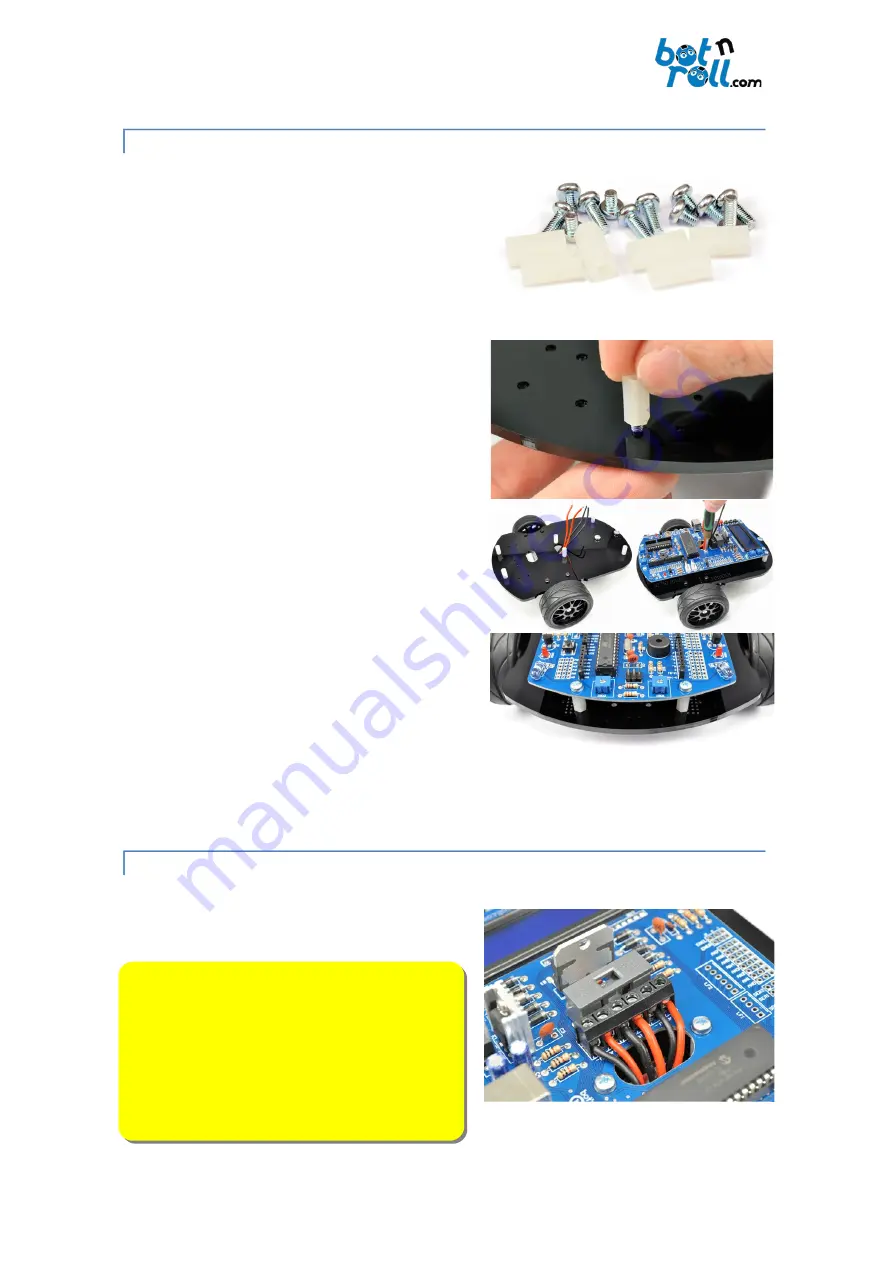
Fixing the robot board to the acrylic base is carried out
by using 6 sets of one 12mm nylon spacer, one M3x8
PH1 screw and one M3x4 PH1 screw.
Insert each M3x8 PH1 screw on the acrylic base from
bottom to top and screw a nylon spacer untl it is
tghtened.
Repeat for each of the six spacers.
Place the electronic board passing the motors wires by
the centre hole and attach it using the M3x4 PH1
screws thru the nylon spacers.
Tighten the screws with a Phillips screwdriver so that
there are no gaps between the PCB, the nylon spacers
and the acrylic base.
4.3.8. CONNECTING THE MOTORS
The connecton of the motors is carried out on the
MotorL
and
MotorR
connectors. The lef motor
connects to
MotorL
and the right one to
MotorR
.
IMPORTANT NOTE:
The motors wires have black and
red colours. Correctly connectng these wires is very
important because polarity determines the motor
directon of rotaton and the robot may not move as
expected!
The red wire must be plugged on the “
+
” and the
black wire on “
–
”.
©Copyright 2018, SAR - Soluções de Automação e Robótca, Lda.
41
Fig. 61: Required parts to hold the PCB
on the acrylic base
Fig. 62: Assembling the PCB on the
acrylic base
Fig. 63: Motors connecton
Summary of Contents for ONE A
Page 1: ......


