9
3. Security Regulations
For lifting machines or parts of machines
with one or more lifting eyes, only hooks
Transporting the complete unit
3.5 Installation on site / Starting /
Normal operation
or shackles complying with local safety
Make sure that the air vessel is not
regulations may be used. Never fasten
cables, chains or ropes to or through lifting
eyes.
Lifting hooks, lifting eyes, shackles etc.
must never be bent and must always be
stressed in alignment with the load-
carrying axis. The load capacity of the
hoisting gear is reduced if the lifting force
is applied at an angle to the axis.
All bearing parts must be stressed
vertically, as far as possible, for maximum
safety and optimum performance of the
hoisting gear. If required, a support is to
be installed between the hoisting gear and
the load. Secure the load properly.
When heavy loads are being conveyed
by means of hoisting gear, it is imperative
to keep well clear of the load in order to
avoid accidents.
Never leave the load suspended on the
hoisting gear.
Acceleration or braking of the means of
transport must remain within the approved
limits.
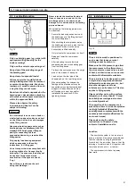
The hoisting gear is to be set up in such
a way that the object is lifted vertically.
Should this not be possible, precautions
must be taken to prevent the load from
swinging. Thus it is possible to use two
sets of hoisting gear, both with an angle of
inclination of not more than 30° to the
vertical.
Nominate experienced supervisors for
the lifting process.
Machines may only be hoisted correctly
using hoisting gear in accordance with the
information in the operating manual (limit
stop points for heavy-lift facilities etc.)
Only use a suitable transport vehicle
with sufficient carrying capacity.
Before or immediately after completion
of loading, secure the machine /
installation to prevent accidental shifting.
Display an appropriate warning. Before
putting the machine / installation back into
operation, the securing devices must be
duly removed.
Parts to be removed for transport
purposes must be carefully refitted and
fixed again before putting the machine /
installation back into operation.
When putting the machine / installation
back into operation again, only proceed in
accordance with the operating manual.
under pressure.
Lift and secure supporting gear.
Make sure that the drawbar eye can
move freely in the tow bar.
Check to make sure that the drawbar is
adjusted to the bar height of the towing
vehicle.
Check to make sure that the body is
closed and locked, and that the cable for
the rapid-emergency brake is connected
to the towing vehicle.
Join up the connections of the air brake,
if present.
Check to make sure that the wheels are
properly tightened, that the tyres are in a
roadworthy condition, that the tyre
pressure is correct and that the brakes
function properly.
Connect the cable for the signalling
and lighting fittings. Check the proper
functioning of the lighting.
Release the handbrake.
Before transporting the unit, always
check to make sure that the accessories
are firmly attached so that they can cause
no accidents!
When using public roads, tracks and
spaces, observe the current traffic
regulations, and if necessary make the
unit roadworthy first!
Never exceed the maximum towing
speed. Observe national regulations!
Always switch on lights if visibility is poor
and during lighting-up time!
When going through underpasses,
bridges, tunnels, overhead power lines,
etc., always make sure that you have
enough clearance!
Always keep a safe distance from the
edges of foundation ditches and
embankments!
Do not travel across slopes transversely:
always keep equipment and loads near
ground level (for example, do not place
them on the bodywork).
On descents, always adapt speed to the
circumstances! Never change into low
gear during the descent, but always
beforehand. When leaving the driver's
seat, always secure the unit to make sure
that it cannot roll away or be used without
authorization!
Avoid all operations that adversely affect
the stability of the unit.
Installation on site
Besides the general technical operation
in accordance with the regulations of the
local authorities, it is essential that the
following guidelines be observed.
Before switching on the machine /
installation, or starting it up, make sure
that nobody can be injured by the
machine / installation as it starts up.
The installation is to be set up in such a
way that it is adequately accessible and
that the necessary cooling is ensured.
Never block the admission of air.
The air intake is to be designed in such
a way that no dangerous admixtures
(inflammable solvent vapors etc., but
also dust and other dangerous or toxic
substances) can be taken in. This also
applies to flying sparks.
The air intake is to be designed in such
a way that no loose personal clothing can
be drawn in.
Make sure that the compressed air line
from the compressor to the air network
can expand as a result of heat and cannot
come into contact with inflammable
materials.
The compressed air line connected at
the air exit of the unit must not be under
strain.
Compressed-air lines have to be marked
distinctly according to local regulations.
If several compressors are arranged in a
system, manually operated valves have to be
installed so that each machine may be
shut off individually. For the purpose of
shutting off pressurized systems, you
should never rely on the effectiveness of
return valves alone.
Safety devices, protective covers, or
insulations mounted on the system must
not be removed or modified in any way.
All pressure tanks located outside the
unit with an approved operating pressure
higher than atmospheric pressure and
fitted with two or more pressure feed lines
must be equipped with an additional
safety device to automatically prevent the
approved operating pressure from being
exceeded by more than 10%.
Pipes and other parts with a surface
temperature of more than 80 °C must be
suitably secured against contact and
suitably marked.
Electrical connections must comply with
local regulations.
With compressors fitted with generators,
use equipotential bonding systems for the
protection of persons.
Summary of Contents for GDP21
Page 8: ...6 2 Foreword Chassis rigid braked Fig 5...
Page 53: ......
Page 61: ......
Page 62: ......


