background image

5. Transport  and  installation  on site

20

5.1  Transport

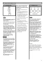
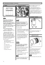
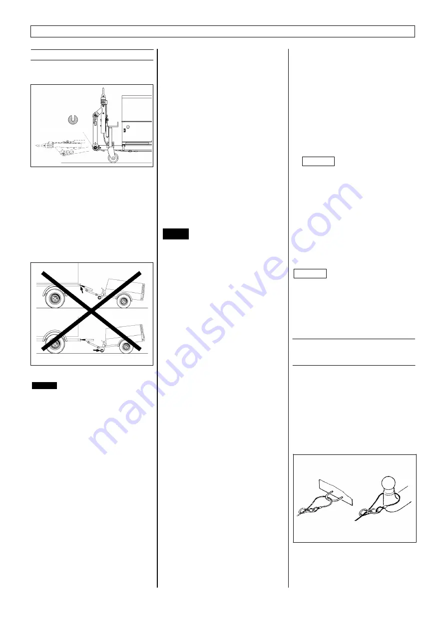
Transport safety locking of the towing
arrangement

Fig. 11

Before moving the compressor for the

first time slacken the ratchet on height-
adjustable towing gear and remove the
transport securement. Then adjust the
towing gear from the vertical transport
position to the required attachment height
for the towing vehicle and lock it in place
in the toothing using the ratchet (see
Section 15. Undercarriage, height-
adjustable towing gear).

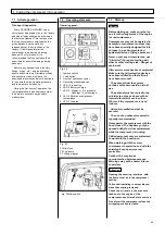
Fig. 12

Danger

Make sure to check the torque after
50 kilometers following wheel
mounting and at regular intervals.

Tighten wheel nuts or screws evenly
in a diagonal sequence to the specified
torque using a torque wrench.

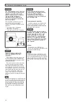
Replacing the trailer coupling ring

The coupling arrangements which can
be used:

*

Trailer coupling ring RD 40

*

Coupling 50 dia.

*

Coupling ring 2" dia. (only for UK)

*

Coupling ring 68 x 25 dia. (only for
France)

A different coupling unit in the form of a

complete kit may be ordered, if necessary.
Replacing the trailer coupling ring is
permitted only if proper fitting is carried out
by  an inspectorate for  the sector  covered
by the Regulations Authorizing the Use of
Vehicles for Road Traffic (e.G. the TÜV -
Technical Inspectorate, DEKRA - German
Motor  Vehicle  Monitoring  Association,
etc.). The inspection station provides  a
fitting certificate to be kept with the vehicle
documents.

The screw compressor may only
be transported on public roads if

*

The machine group (engine) is
not running,

*

The pressure tank is not under
pressure,

*

The shielding is closed,

*

The blocks are firmly hooked in
place,

*

Hoisted and secured tail wheel,

*

The tyres and brakes are
operationally safe and roadworthy,

*

The lighting is fully functional.

Never exceed the maximum towing
speed! Danger! Observe national
regulations!

Please also observe the safety
instructions in Chapter 3 on the
subject of transporting.

Before transporting the compressor,

check to make sure that the draw gear of
the towing vehicle and the drawbar eye or
trailer hitch ball connection are aligned
exactly  to  each other.

When transporting the screw compressor
with a vehicle, the following points must
be observed:

*

The shielding is closed.

*

The blocks are firmly hooked in place.

*

The support(s) is(are) retracted and
locked in position (jockey wheel).

*

Drawbar is connected to the towing
vehicle.

*

The drawbar is adjusted to the height
of the towing vehicle (option).

*

The contact-breaking cable is
connected to the towing vehicle. Safety
chains  are  attached on towing  vehicle.

*

The electrical cable (option) is
connected to the vehicle and to the
screw compressor .

*

Check the lights (tail lights, brake
lights, indicator lights, and rear fog
lamp) (option).

*

Check to make sure that the wheels
are properly tightened, the tyres are in
a roadworthy condition.

Check tyre pressure, and adjust if
necessary (risk of accident). A too
high tyre pressure can lead to
overstraining  of  safety parts.

*

When parking the compressor prior to
uncoupling from the towing vehicle
actuate the handbrake, detach the
contact-breaker cable and the lighting
cable, and secure the compressor
against rolling using chocks. Then
adjust to the horizontal position by
means of a support or support  wheel.

Always keep a safe distance from the
edges of foundation ditches and
embankments! Do not travel across
slopes transversely.

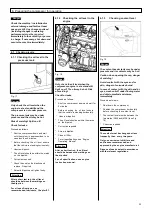
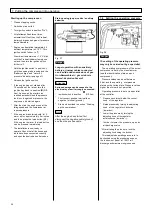
5.2  Attachment of the contact-

breaker cable on braked
chassis

If the towing connection becomes

uncoupled, the trailer is braked by the
breakaway cable. Put the breakaway  cable
in the eye provided or wind it around the
towing collar and hitch it up to the    cable
with the snap link.

The breakaway cable must be attached

in a way that ensures that even on
extremely sharp bends there is no danger
of activating the locking brake.

Fig. 13

Danger

Attention

Attention

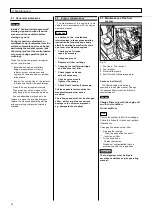
   Transport safety locking

Summary of Contents for GDP21

Page 1: ...OR ALL THE INQUIRES PLEASE COMMUNICATE THE TYPE OF THE UNIT AND THE SERIAL NUMBER THAT CAN BE FOUND ON COMPRESSOR INFORMATION PLATE FOR INFORMATION AND SPARE PARTS G DP 21 GDP3 1 MANUFACTURED BY COMPR...

Page 2: ...CALIFORNIA Proposition 65 Warning Diesel engine exhaust and some of its constituents are known to the State of California to cause cancer birth defects and other reproductive harm...

Page 3: ...the contact breaker cable on braked chassis 20 5 3 Loading Relocation 21 5 4 Installation on site 21 6 Preparing the compressor for operation 23 6 1 Checking levels 23 6 1 1 Checking the oil level in...

Page 4: ...rator switchbox wiring diagram GTS 400 230V 8kVA 44 11 12 Generator switchbox wiring diagram KWG 110V 7kVA 45 11 13 Generator switchbox wiring diagram KWG 230 400V 8kVA 45 11 14 Troubleshooting 46 12...

Page 5: ...for its intended purpose The compressor is not operated by trained personnel Unauthorized changes or modifications are carried out on the compressor You are not wearing the prescribed protective clot...

Page 6: ...ed air connections max permissible noise level acc to 2000 14 EC max sound intensity acc to PN8NTC 2 2 at the operators location distance 1m max sound intensity acc to PN8NTC 2 2 distance 7m 1 Chassis...

Page 7: ...5 2 Foreword Chassis height adjustable braked Fig 2 Chassis height adjustable unbraked Fig 3 Chassis rigid unbraked Fig 4...

Page 8: ...6 2 Foreword Chassis rigid braked Fig 5...

Page 9: ...tional regulations for accident prevention and environmental protection It must always be available at the site of the compressor The operating manual is to be read and used by all persons in charge o...

Page 10: ...essure temperature time settings etc must be permanently marked Personnel selection and qualification basic tasks Work on or with the machine Define who is responsible for operating the machine and au...

Page 11: ...it always check to make sure that the accessories are firmly attached so that they can cause no accidents When using public roads tracks and spaces observe the current traffic regulations and if neces...

Page 12: ...f devices are in perfect condition and are not blocked for example by dirt or paint The safety devices all work properly All connected components must be of the correct size and be suitable for the sp...

Page 13: ...ntenance work All maintenance and repair work may only be carried out when the system is shut down or with electrical systems when the mains power supply is switched off Make sure that the equipment c...

Page 14: ...or similar device During assembly work above body height use appropriate or otherwise safety relevant climbing aids and working platforms Do not use machine parts as climbing aids Wear safety belts wh...

Page 15: ...n closed rooms Always adhere to the legal provisions applicable to the particular location Follow the local regulations applicable at the respective site of installation Hydraulic and pneumatic system...

Page 16: ...aution Hot and dangerous exhaust fumes 100003144 Caution Do not use ether spray A93634770 A93634780 Sound level data Hoisting point Tie down point Caution Do not move with the transport safety locking...

Page 17: ...xpansion tank 8 Engine actuating cylinder 9 Fuel filter including drain valve 10 Fuel tank 11 Crane ring 13 Air filter 14 Battery 15 Oil filter compressor 16 Proportional controller 17 Main switch 18...

Page 18: ...l preseparation of the oil is ensured through tangential entry into the tank Any remaining oil is separated from the air in the fine separator The compressed air is fed via the pressure retention valv...

Page 19: ...switch 13 Orifice evacuation line 14 Oil cooler compressor oil 15 Pressure tank 16 Fine separator 17 Safety valve 18 Pressure retention valve 19 Air bleeding cock 1 x 3 4 2 x 3 4 20 Pressure gauge 21...

Page 20: ...nitoring unit Generator Generator controller Starter Lifting magnet Generator controller Solenoid valve Generator Solenoid valve Pre heating Oil Motor Compressor pressure relief option generator idlin...

Page 21: ...tacts 1 8 Indicator right green Indicator right Tail light right brown Tail light right Number plate light Brake light right Brake lights red Brake light left Number plate light Tail light left black...

Page 22: ...observe the safety instructions in Chapter 3 on the subject of transporting Before transporting the compressor check to make sure that the draw gear of the towing vehicle and the drawbar eye or trail...

Page 23: ...hat the compressor which must be set up horizontally is lifted vertically Only relocate the compressor by itself Raise and lower the compressor carefully After relocating remove the load suspension de...

Page 24: ...el No force may be exerted on the dis charge valves for example by pulling the hoses or fitting additional equipment e g a water separator compressed air oiler etc directly at the discharge valve Temp...

Page 25: ...s Shut the compressor down and wait for 5 minutes Before checking the oil level ensure that the vehicle is standing horizontally Unscrew dipstick The oil level should be within the marks on the dipsti...

Page 26: ...4 Fuel water separator Only fill up with fuel when the screw compressor is at a standstill Cleanliness is essential Spill no fuel Filling up at a pump can cause static electricity and possibly sparks...

Page 27: ...of the engine screw compressor Compressors may not be operated in hazardous environments unless they have been specially designed for this purpose e g exhaust protected against emission of flying spa...

Page 28: ...setting of the operating pressure may only be carried out by a specialist The operating overpressure of the screw compressor is set by the manufacturer see the identification plate on each compressor...

Page 29: ...bove the permissible operating pressure The pressure gauge shows the operating pressure of the compressor The permissible operating pressure is indicated on the nameplate the specified operating press...

Page 30: ...wn to 50 C for use with maximum and minimum operating temperatures given in this operating sound absorbers manual only apply when high quality multi grade oils are used Use of the wrong oil leads to i...

Page 31: ...he coolant consists of 50 water and 50 corrosion protection antifreeze fluid Use drinking water only Do not use sea brackish industrial rain or distilled water The coolant should be changed not less f...

Page 32: ...nstruction the following items apply after 50 operating hours after the start up of new or overhauled engines Check engine for leaks repair if necessary Change engine oil Replace oil filter cartridge...

Page 33: ...e hot particularly the exhaust system risk of burning and that the control device may move during operation risk of crushing Danger Change the fuel water separator only with the engine off and in cool...

Page 34: ...ir filter screwcompressor motor Change oil filter of the screw compressor Oil change screw compressor Inspect automaticoperationalmonitoring Change fine separator everyyear orifdifferentialpressure 1b...

Page 35: ...l drain valve Unscrew the sealing cap of the pressure vessel Collect used oil in the oil drain pan When the used oil has been drained completely use a new sealing ring on the sealing screw of the pres...

Page 36: ...rtridge The maintenance intervals of the air filter depend on the environmental conditions If the red field of the maintenanceindicator is visible and stays engaged when the screw compressor is turned...

Page 37: ...for maintenance purposes Designation Identification No fill up with distilled water if necessary For battery maintenance please also refer to the manufacturer s instructions and the engine operating m...

Page 38: ...r or replace Air short circuit Repair No power on instrument panel Switch on fuse F1 Operating voltage low Charge battery or replace Electrical connection loose corroded or broken Replace Starter defe...

Page 39: ...controller defective Repair or replace Other engine problems See engine operating manual Oil in air line Orifice in oil return line clogged Repair clean Oil fine separator defective Replace Too much o...

Page 40: ...80 C This compromises the connected devices which must be switched off or unplugged immediately Always avoid operating the generator under such conditions and keep it clean particularly fan cowl air i...

Page 41: ...dicator lamp for Insulation fault to light up must not be connected to other generators without insulation monitoring or to the public mains Have equipment with insulation faults immediately replaced...

Page 42: ...ngine speed Compressed air and electrical power can be consumed up to maximum engine speed Note that engine speed is reduced in the event of an overload Compressed air mode without consumption of elec...

Page 43: ...output 0 8 cap ind 7000VA Nominal current 32A 2 x 16A Startup current 4 1 times Irated Operating mode S1 continuous Protective measure Electrical isolation with equipotential bonding conductor in acc...

Page 44: ...ection IP 54 Dimensions 255x205x134mm Design Front panel type Fusing All poles U1 AS32A U2 2 x AS16A Insulation monitoring Model KWG ISO 001 Controls Red test button Green reset button Areas of applic...

Page 45: ...phase 11 6A Startup current 4 1 times Irated Operating mode S1 continuous Protective measure Electrical isolation with equipotential bonding conductor in accordance with VDE 0100 728 Coolant Air exter...

Page 46: ...t button Green reset button Electronic evaluation system Integrated on the generator controller Speed reduction Activation 75W Time to speed reduction 100 seconds Outputs Output for speed reduction Po...

Page 47: ...SS II SEE OPERATING MANUAL AC L Load AC L Load AC L Load PROTECTIVE ISOLATION WITH INSULATION MONITORING AND FUSING CIRCUIT BREAKING FOR ALL POLES K OPERATING CURRENT CIRCUIT BREAKER H INSULATION FAUL...

Page 48: ...r switchbox wiring diagram KWG 230 400V 8kVA Fig 46 RED 1 GREY 2 BLUE 6 YELLOW 3 YELLOW 4 YELLOW 5 BROWN 1 BROWN 2 BLACK 5 BLACK 6 BLUE 3 BLUE 4 GREEN YELLOW 7 FUSE 5A RED 1 GREY 2 ORANGE 8 YELLOW 3 Y...

Page 49: ...connected devices Reset the circuit breaker Plug in devices one after the other Is insulation monitoring still enablend yes no no Connected devices are faulty Has fuse blown yes Unplug connected devic...

Page 50: ...eck connected electrical loads for short or earth contact Do not operate the generator at nominal output see the operating instructions for the engine Compressor operating pressure set too high Re adj...

Page 51: ...rating manual The heat exchanger operates fully automatically Operating errors at the heat exchanger are excluded 12 2 Design and operation With the aid of the compressor oil the compressed air whose...

Page 52: ...remaining condensation must be drained from the secondary cooler For doing this the bottom cover of the secondary cooler must be opened and it must be emptied utilising the pressure remaining in the...

Page 53: ......

Page 54: ...on See page 17 Fig 8 for system function diagram With the aid of the oil temperature controller the compressor oil circuit is kept at an optimum service temperature The oil temperature controller regu...

Page 55: ...please check the compatibility with our Technical Department Model details must not be obscured by paint now concealed by components torque depends on the permitted gross weight of the trailer and th...

Page 56: ...htly pre tensioned and must not become fully compressed when activated Bowden cable 14 must not activate brake Never readjust the braking system or brakes by the brake linkage 6 or turnbuckles if fitt...

Page 57: ...ettle the braking system Check the position of the brake compensating balances 9 and 10 which should be at right angles to the direction of towing Recheck the play in the linkage 6 if necessary adjust...

Page 58: ...nces problems were to occur with these bearings completely new brake drums with pressed in bearings circlips and new locking nuts should be installed in principle Due to the design characteristics of...

Page 59: ...ightly Re adjust brake system even impossible Bowden cables pre loaded Re adjust brake system Backmat brake shoe is jammed in the brake shoe holder Replace compl brake shoes with brake shoe holders Br...

Page 60: ...ble at the adjusting knob Turning the adjusting knob clockwise symbol will reduce the oil flow up to 0 quantity i e no oil for tool lubrication in the compressed air Turning the adjusting knob counter...

Page 61: ......

Page 62: ......
Reviews: