


Dari-Kool III-120 Instructions
3
1E-138B
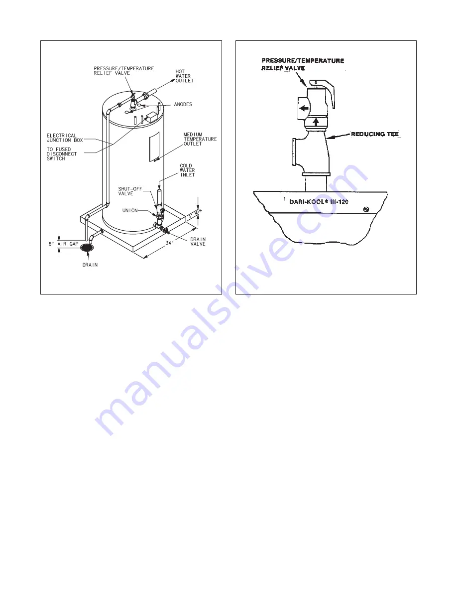
Figure 1. Dari-Kool III-120 Plumbing l138_1
Figure 2. Pressure/Temperature Relief Valve Installation
Important Note: A temperature and pressure relief valve is for
protection against both excessive temperature and pressure; and
if either of these conditions develop in the system, the valve will
open and discharge water. ( label P/N 4016124)
4. The optional water valve limits the water temperature when
refrigerant heat input is too high. It should be installed to bleed
water to the drain or to a suitable alternate point of usage such
as a heat exchanger or reservoir. This normally-open valve is
closed only when energized, so it will be open when the water
in the Dari-Kool III-120 reaches the thermostatic set point. It
will also be open if a power outage occurs. Considerations
should be made to accommodate a flow rate of 40 gallons
(151 L) per hour. See Figure 3 for the preferred installation.
See the electrical section for wiring instructions.
5. To fill the Dari-Kool III-120: Close the drain valve and open a
hot water tap to bleed the air from the tank as it fills. Open
the inlet water valve. Allow sufficient time for the tank to fill,
as indicated by a steady flow of water, then close the water
tap and check for leaks.
6. If the solenoid water valve is used, power will have to be
applied to the valve in order to close it while checking
for leaks. DO NOT apply power to the heating element unless
it is covered with water.
7. The Dari-Kool III-120 has dual magnesium anode protection.
Under certain water conditions, an offensive odor may be
noticed after the system is in operation. To eliminate this odor,
remove the magnesium anodes and install aluminum anodes
(Part No. 4016425).
— Note ———————————————————————
ALTERNATE PRESSURE/TEMPERATURE RELIEF VALVE.
In the event that the combination pressure/temperature relief valve
is lost or damaged, an alternate device may be used providing it:
•
has a minimum thermal rating of 100,000 BTUH (3 kW hours)
•
has a maximum pressure rating of 150 PSIG (1000 kPa)
•
is certified as meeting the requirements of ANSI Z231.22, by a
nationally recognized testing laboratory.
4.
Installing the Refrigeration System
4.1
Installation Layout
The Dari-Kool III-120 is designed for use in refrigeration
systems that have adequately-sized air-or water-cooled
condensors. The Dari-Kool III-120 should be installed
between the compressor and condensor. A number of possible
combinations are shown in Figures 6-12.
— Note ———————————————————————
Capillary tube systems are not normally recommended for use
with Dari-Kool. For special considerations, please contact the
factory.
4.2
Refrigerant
The Dari-Kool III-120 desuperheater plate is designed for
low pressure drop. Each of the two sections of the plate will
handle up to 7.5 tons (26 kW) of R-22, R-404, R-407, or 5
tons (17.5 kW) of R-134A.


