


1E-138B
4
Dari-Kool III-120 Instructions
1. If cabinet openings or modifications have to be made,
they must be accomplished in such a manner as not to
be detrimental to the cabinet. Do not cut into electrical
enclosures.
2. Do not route tubing through electrical enclosures or cabinet
sections containing live metal parts. The tubing
must be properly supported and protected from sharp edges
and moving parts.
3. The tubing must be mechanically isolated from structural
building members.
— Note ———————————————————————
• Be careful not to burn wrapper on insulation when brazing
refrigeration lines.
• All joints should be checked for leaks and the lines evacuated
according to standard refrigeration practices.
Figure 3. Water Valve Installation
4.3
Refrigerant Lines
The compressor discharge line size is usually adequate for
normal installations. However, if lines are more than 20 feet
(6 m) long, they should be sized for a maximum of 15 PSIG
(103 kPa) pressure drop. (See ASHREA piping tables.) Lines
should be installed to pitch toward the Dari-Kool III-120 and
condensor, and to drop down from the compressor discharge
to form a 6” (152 mm) trap to prevent oil and liquid refrigerant
from accumulating on the discharge valve plate.
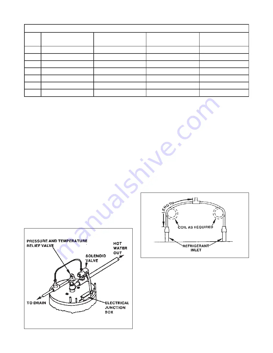
When two circuits of the Dari-Kool III-120 are connected to
a single compressor, it is important to size the inlet tubes to
create a small but equal pressure drop. This small pressure drop
is required to insure equal distribution through each circuit.
This is important to achieve optimum performance, and to
prevent oil and liquid trapping. See the following table for
recommended line sizes. These diameters and lengths should
create about a 5 PSI (34 kPa) pressure drop.
When installing a Dari-Kool III-120 on an existing refrigeration
installation, extreme care must be used not to damage the
existing system. If the tubing must be routed into an existing
cabinet, the following precautions must be taken:
Figure 4. Manifold for single compressor Installation on inlets only.
Table 1: Recommended Line Sizes
HP
R-134A Dia.
Length
R-22 Dia.
Length
2
1/4” (6 mm)
12' (4 m)
1/4' (6 mm)
36' (11 m)
3
5/16” (8 mm)
28' (9 m)
1/4' (6 mm)
12' (4 m)
4
5/16” (8 mm)
12' (4 m)
5/16' (8 mm)
36' (11 m)
5
3/8” (10 mm)
30' (9 m)
5/16' (8 mm)
20' (6 m)
6
3/8” (10 mm)
24' (7 m)
−
−
7-1/2
3/8” (10 mm)
12' (4 m)
3/8' (10 mm)
36' (11 m)
10
−
−
3/8' (10 mm)
12' (4 m)


