Manual Current relay print JGA2011
Boutronic B.V.
Boutronic B.V.
Page - 3 -
’
s-Gravenzande The Netherlands
Connections
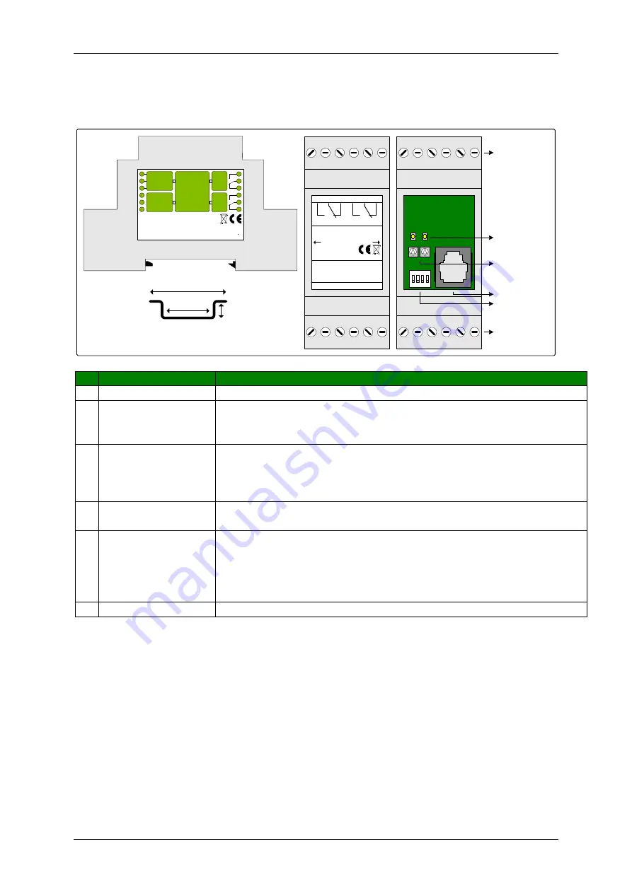
The figure below shows schematically the JGA2011:
4: Firmware poort
2: LED
3: Potentionmeters
1
O N
2 3
4
L1
L2
P1
5: Dipswitches
6: Connections 1 to 6
1: Connections 7 to 12
35,0 mm
25,0 mm
7,5 mm
Top hat rail IEC/EN 60715
DIP 1...4
7
8
9
10
11
12
1
2
3
4
5
6
C
O
N
TR
O
L
Powe rsuppl y
www. boutroni c.nl
GN D
+24VDC I N
Type nummer JGA2011
+ 24VDC O UT
4-20m A in 2
GN D
Inputs 4-20m A
RoHS complia nt
T A : 0 . .. 70 C
Relay 1
Re lay 2
4-20m A in 1
Re lay contacts
: 24VAC/DC m ax 1000mA
: 24VDC 50mA
: R-loa d = 500 Ohm
7
8
9
10
11
12
1
2
3
4
5
6
RoHS compl ia nt
T ype JGA2011
G
N
D
4
-2
0m
A
I
N
2
Rela y 2
G
N
D
4
-2
0m
A
I
N
1
Rela y 1
+
24
V
D
C
IN
+
24
V
D
C
O
U
T
www.boutronic.nl
M ade in the N etherlands
Li ft front here for ac ces s control
P2
Nr
Unit
Description
1
Connection 7 … 12
Connection 7 … 12, see front for type of connections
3
LED
These LEDs indicate whether the value of the corresponding input is above
or below the switching threshold. The burning time of the LED corresponds
to the set delay (default 1 sec). After this time, the relay switches.
2
Potentiometer
Potentiometer for setting the switching threshold of the relays
P1: Relay 1
P2: Relay 2
When DIP-switch 3 is ON, a software delay is used.
4
Firmware port
Connection to PCB (with a Boutronic dongle) for firmware update
or programming settings
5
DIP-switches
DIP-switch 1: reserved
DIP-switch 2: reserved
DIP-switch 3: Time with potentiometer or software
DIP-switch 4: reserved
See chapter
change settings
6
Connection 1 … 6
Connection 1 … 6, see front for type of connections


