76
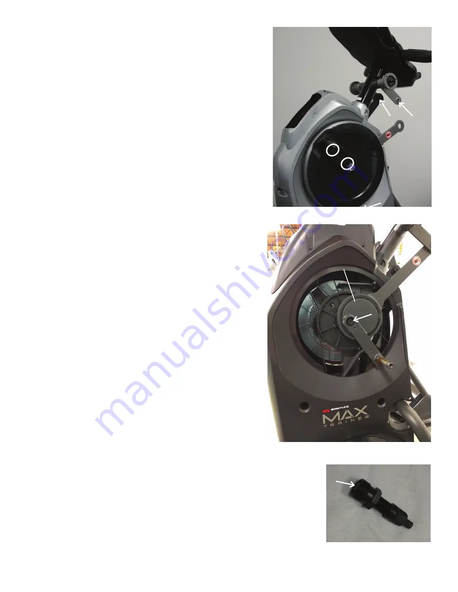
10. Using a #2 Phillips screwdriver, remove the 2 indicated screws
(by ovals) from the Left Crank Cover.
Note:
The image displays the Right Crank Cover being removed.
11. Remove the Left Crank Cover from the machine.
12. Place a rag or protective material below the Left Connector Arm
to protect the Shroud from potential scratches from the Connector
Arm.
13. Using a 6mm hex wrench, remove the indicated hardware (with
arrows) that connects the Left Connector Arm and the Pivot Arm.
Note:
The Connector Arm will pivot downward if not lowered slowly
onto the rag protecting the Shroud.
14. Using a 9/16” or 14mm socket and wrench, remove the nut from
the Left Crank Assembly.
15. Adjust the Crank Puller until the end of the Bolt is flush with the
Nut (as shown).
16. Carefully thread the Crank Puller into the Left Crank Arm. Be sure
the Crank Puller has at least three rounds of threads inserted.
Left Crank Assembly
Crank Cover
Pivot Arm
Connector Arm


