background image


 Rev D 

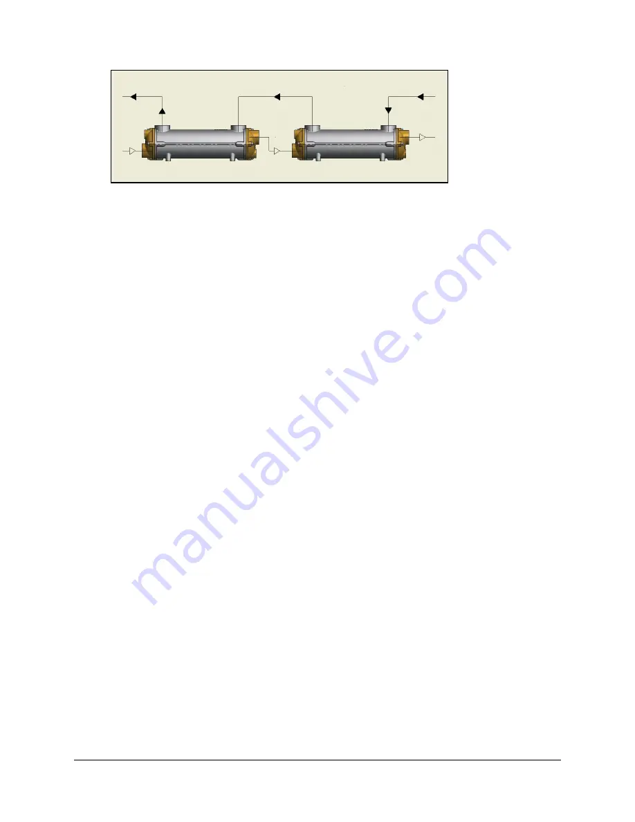
Or in series: 


A filter with a maximum permeability of 2.0mm should be used prior to the inlet of each circuit of the 

oil cooler.  
Nothing should be welded to any part of the oil cooler.  Each unit has threaded holes on its underside to 

facilitate mounting.  


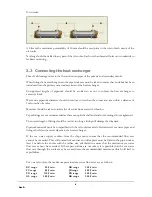
2.3  Connecting the heat exchanger 


Shut off all drainage valves in the flow and return pipes of the primary and secondary circuits. 

When fitting the heat exchanger into the pipe work care must be taken to ensure that no debris has been 

introduced into the primary or secondary circuit of the heat exchanger. 

Unsupported  lengths  of  pipework  should  be  avoided  so  as  not  to  subject  the  heat  exchanger  to 

excessive loads. 

Water side pipework diameter should not reduce to less than the connection size within a distance of 

1m from the oil cooler. 

Measures should be taken to isolate the oil cooler from excessive vibration. 

Taper fittings are not recommended as these can split the shell and end cover castings if over tightened. 

The correct length of fitting should be used as too long a fitting will damage the tubestack. 

Pipework materials must be compatible with the oil cooler materials. Stainless steel sea water pipes and 
fittings should not be used adjacent to the heat exchanger.  

If  the  sea  water  supply  is  taken  from  the  ships  main,  ensure  that  the  recommended  flow  rate 
cannot be exceeded. This will normally mean that an orifice plate must be fitted in the pipe work at 

least 1m before the cooler with the orifice size calculated to ensure that the maximum sea water 
flow rate cannot be exceeded. If these precautions are not taken, it is possible that the sea water 

flow rate through the cooler may be several times the recommended maximum which will lead to 
rapid failure. 


For our oil coolers, the maximum permitted sea water flow rates are as follows: 


EC range 

  50 l/min. 


GK range 

300 l/min. 


FC range 

  80 l/min. 


JK range 

400 l/min. 


FG range 

 110 l/min. 


PK range 

650 l/min. 


GL range 

200 l/min. 


RK range 

900 l/min. 

Summary of Contents for EC Series

Page 1: ...HYDRAULIC OIL COOLER Installation Operation Maintenance Guide REG NO FM 38224 BS EN ISO 9001 2008 ...

Page 2: ...o ensure the long lasting performance from your new Hydraulic Oil Cooler Copies of the Hydraulic Oil Cooler brochure are available in other languages from French German http www ejbowman co uk downloads htm Italian Spanish All rights reserved E J Bowman Birmingham Ltd reserve the right to change specification and technical alteration without prior notice No part of this guide may be reproduced or ...

Page 3: ... E R A T I O N 8 4 C O M M I S S I O N I N G 8 5 M A I N T E N A N C E R E P A I R 5 1 Winter shut down in areas exposed to frost 9 5 2 General maintenance 9 5 3 Cleaning 9 5 4 End cover bolt tightening sequence 10 6 P O T E N T I A L S E R V I C E I S S U E S 6 1 Tube failures 10 6 2 Fault finding 11 7 W A R R A N T Y 11 8 S P A R E P A R T S 11 9 C E M A R K I N G 12 E J Bowman Birmingham Ltd Ch...

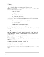
Page 4: ...tended purpose In the event of breakdowns which may compromise safety a suitably qualified person must always be contacted 1 2 Approved use BOWMAN Hydraulic Oil Coolers are only approved for cooling hydraulic oil Any other use unless specified by BOWMAN is not approved BOWMAN declines all liability for damage associated or arising from such use The maximum permissible operating pressure must not e...

Page 5: ...mise fluid loss 2 Installation 2 1 Transport storage The heat exchanger must be fully drained down prior to transportation Once drained and fully dry the heat exchanger must only be stored indoors within a non aggressive atmosphere The connections should be capped to avoid ingress of dirt and contaminants 2 2 Fitting Before fitting the heat exchanger should be checked for visible signs of damage T...

Page 6: ...er fittings are not recommended as these can split the shell and end cover castings if over tightened The correct length of fitting should be used as too long a fitting will damage the tubestack Pipework materials must be compatible with the oil cooler materials Stainless steel sea water pipes and fittings should not be used adjacent to the heat exchanger If the sea water supply is taken from the ...

Page 7: ...admiralty brass tube or its variants The purpose of the zinc anode or zinc pencil as it is sometimes called is to prevent dezincification of the brass alloy tubes As such zinc anode acts sacrificially in favour of the tube There are a number of American and European manufacturers that use these anodes in their products Bowman do not fit zinc anodes as the tubes used in the construction of our cool...

Page 8: ...st be adequately vented from both circuits f Stagnant water should not be allowed to accumulate in the oil cooler If it is not in use for any period of time the water should be drained off 4 Commissioning Commissioning of the heat exchanger should not be undertaken until such time that this document has been fully read and understood The primary and secondary circuits of the heat exchanger must be...

Page 9: ... solution can be circulated through the heat exchanger or the unit can be disassembled and the tubestack submerged in a container filled with cleaning fluid If necessary the fluid should be neutralized after cleaning and the unit should be flushed with fresh water and dried Small diameter rods and brushes for tube cleaning are available from companies such as Easy Products www easyproductsltd com ...

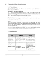
Page 10: ...ter is stagnant Low sea water flow rates can create a high temperature rise on the sea water side Under these conditions deposits may build or settle in the tube allowing pitting corrosion to take place under the deposits This is only a brief introduction to corrosion problems The subject is complex and the purpose of these notes is to outline in very general terms what may occur under extreme con...

Page 11: ...arts A comprehensive stock of spare parts is always available Details are given in the Hydraulic Oil Coolers brochure which can be downloaded from http www ejbowman co uk products HydraulicOilCoolers htm Please contact our sales department for price and availability or nearest stockist 9 CE Marking Documentation Heat exchangers are covered by the Pressure Equipment Directive 97 23 EC which is mand...

Page 12: ...followingindustries CHP Power Generation Engine Test House Cooling Marine Cooling Swimming Pool Heating Fishing Industry Cooling The product range includes Aquatic Heat Exchangers Calorifiers Exhaust Gas Heat Exchangers Plate Type Heat Exchangers Shell Tube Oil Coolers Stainless Steel Heat Exchangers Swimming Pool Heat Exchangers ...

Reviews: