background image


29/09/2016

03

8 / 8 

SEQUENZA DI FUNZIONAMENTO
FUNCTIONING SEQUENCE

Per ruotare la gamba

tirare il pomello nero


To rotate the leg,

pull the black knob

Per richiudere le guide,

spingere le leve rosse

(una per ciascun lato)


To close the slides,

push the red levers

(one for each side)

Per far rientrare la parte

inferiore della gamba

spingere il pulsante indicato


To close the inferior part

of the leg, push the

indicate button.

Summary of Contents for T-ABLE

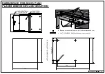
Page 1: ...KAGING SACCHETTO ACCESSORI ACCESSORIES A Chiave esa n 3 n 3 Allen key B Chiave esa n 4 n 4 Allen key C Chiave esa n 5 n 5 Allen key D Distanziale per spalla Side spacer x 20 E Bussola in ottone M6 12x8 mm M6 12x8 mm brass bush x 12 F Vite TCBCE M5x10 ISO 7380 M5x10 ISO 7380 screw x 8 G Vite TCCE M6x12 M6x12 socked head cap screw x 12 H Vite TPS M6x16 M6x16 screw x 2 I Vite trilobata M6x25 M6x25 se...

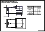
Page 2: ... 3 CODICE CODE MODULO MODULE L1 MIN MAX mm L2 mm L3 mm 411 78 1900 22 600 560 570 426 478 411 78 1910 22 900 860 870 726 778 411 778 1920 22 1200 1160 1170 1026 1078 1311 5 MASSIMA ESTENSIONE APERTO MAXIMUM LENGTH OPENED INTERASSE PER FISSAGGIO PIANO L3 DISTANCE BETWEEN PLANE FIXING HOLES DISTANZA TRA LE GUIDE L2 SPACE BETWEEN THE SLIDES LARGHEZZA L1 WIDTH MAX LUNGHEZZA DA CHIUSO 540 MAX OVERALL L...

Page 3: ... MIN 540 mm LARGHEZZA INTERNA MODULO CABINET INTERNAL WIDTH L MIN 560 mm MAX 1170 mm SPESSORE SPALLA SIDE THICKNESS S1 15 20 mm SPESSORE PIANI PLANES THICKNESS S 18 22 mm LARGHEZZA PIANI PLANES WIDTH Z L 5 mm APERTURA MAX PIANI MAX OPENING PLANES E 895 mm APERTURA MAX MECCANISMO MAX OPENING MECHANISM C 770 mm ALTEZZA DA TERRA HEIGTH FROM GROUND T MIN 745 mm MAX 815 mm H P C E 529 420 R420 S T Z S1...

Page 4: ...m 2 distanziale Spalla da 17 mm 3 distanziale Spalla da 16 mm 4 distanziale Spalla da 15 mm 5 distanziale Side thickness 20 mm no spacer Side thickness 19 mm 1 spacer Side thickness 18 mm 2 spacers Side thickness 17 mm 3 spacers Side thickness 16 mm 4 spacers Side thickness 15 mm 5 spacers La quota indicata di 53 mm lascia uno spazio tra lato inferiore guide e pianetto sottostante di circa 25 mm T...

Page 5: ...IONS AND MOUNTING 406 529 Z Z L3 VEDI PAG 2 SEE PAG 2 280 8 4 X 1 3 VISTA DAL BASSO BOTTOM VIEW E Bussola in ottone M6 12x8 mm M6 12x8 mm brass bush x 4 J Vite TCCE M6x60 M6x60 socked head cap screw x 4 J E PIANO FISSO FIXED PLANE PIANO RIBALTABILE TILTING PLANE ...

Page 6: ...29 09 2016 03 6 8 MONTAGGIO DEL MECCANISMO SUL MOBILE MOUNTING OF THE MECHANISM ON THE CABINET G Vite TCCE M6x12 M6x12 socked head cap screw x 8 G G ...

Page 7: ...ut 25 mm Usare chiave da 3 per avvitare e svitare questi due grani 1 per lato e fissare la parte inferiore della gamba in una delle tre posizioni disponibili Use the n 3 allen key to screw and unscrew this grain and positioning the lower part of the leg in one of the three allowable positions MONTAGGIO DI TRAVERSO PIATTONE E GAMBE CONNECTION BAR PLATE AND LEGS ASSEMBLY G Vite TCCE M6x12 M6x12 sock...

Page 8: ...ro To rotate the leg pull the black knob Per richiudere le guide spingere le leve rosse una per ciascun lato To close the slides push the red levers one for each side Per far rientrare la parte inferiore della gamba spingere il pulsante indicato To close the inferior part of the leg push the indicate button ...

Reviews: