PRE-ASSEMBLY
1. Cut the red & black wires on the JST connector so the total
length (including the JST) is 2-1/4”. The yellow wire to 5”
and pull out the Blue wire completely.
2. Cut the Black ground wire to 2-1/4”
3. Cut the White 510 wire to 2-1/2”
4. Cut the White Jumper wire to 3”
5. Cut 2 pieces of the Black 16 AWG to 1-3/4” each
6. Cut 2 pieces of heat shrink to between1/2” - 3/4”
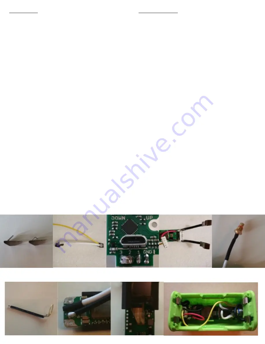
7. Bend the 4 battery contacts at a 45 degree angle as shown
in Figure A.
ASSEMBLY
8. Take the jumper wire and solder a battery contact to one
end and both a battery contact and the Yellow JST wire to
the other side as shown in Figure B.
9. Solder a battery contact to the end of a 1-3/4” Black wire,
repeat for the 2nd wire.
10. Solder the JST connector to the chip, bridging terminals 2
& 3 as shown in Figure C
11. Solder one 1-3/4” wire along with the Red wire from the
JST to the B+ pad on the chip as shown in Figure D
12. Solder one 1-3/4” wire along with the Black wire from the
JST to the B- pad on the chip as shown in Figure D
Kit Contents:
•
1-pc Boxer Enclosure (Case, Battery Sled, Cover)
•
1-pc Evolv DNA200 Chip (with screen & JST conn)
•
1-pc Fat Daddy v4 Low Profile Spring Loaded 510
•
1-pc JST connector
•
3-pc Screws
•
4-pc Battery Contact
•
2-pc 16 gauge Silicone Wire
•
1-pc Heat Shrink Tubing
Before You Begin:
•
Check All Contents.
* Note: The enclosed instructions are just for reference purposes
only. You should NOT attempt to build this mod if you are not an
expert at soldering or building mods. By following these
instructions or building this mod in whatever way you choose, you
agree to all assumptions of risk and voluntarily release, discharge,
waive and relinquish any and all actions or causes of action for
personal injury, property damage, death, or loss of any kind
whatsoever occurring to yourself as a result during both building
this mod and your continued use of it.
Instructions:
Figure C
Figure E
Figure F
Completed
Figure A
13. Unscrew center adjustable pin of 510 and solder to the
white wire, being careful NOT to solder to the bushing (or
you will not be able to adjust 510). Slide up heat shrink to
cover & shrink it as shown in Figure E.
14. Take 510 washer and bend down 90 degrees, just past the
hole opening.
15. Take the Black 16 gauge wire (2-1/4”) and solder to the
outside of the 510 washer as shown in Figure F.
16. Place 2nd piece of heat shrink on the White 510 wire and
solder to the chips pad labeled OUT and the ground wire
to the pad labeled GND as in Figure G.
17. Using double sided tape or silicone attach the Evolv screen
to the screen holder and then attach the flat end to the
chip and the holder around the ends of the chip as shown
in Figure H
18. Remove the screen protector of the DNA200 display and
place board into enclosure aligning all 3 screw holes. Then
screw in each of the 3 screws.
19. Attach the 510 connector to the enclosure and the
adjustable pin into the body
20. Push in all 4 battery contacts into the enclosures recessed
channels.
21. Attach the Enclosure’s Battery Sled & Door
22. Setup in eScribe to your personal liking, being sure to
change to 2 cell configuration & Enjoy!
Figure G
Figure H
Figure D
Figure B


