Service Manual 04/2010 Rev.B
105
L
:
Incorrect saddle adjustment may cause the
following malfunctions:
1. Excess of saddle play.
2. Incorrect distance between tool and rim.
3. Low bead breaking power.
TO CHECK THE ADJUSTMENT:
To control the adjustment
6.6.
TO ADJUST THE SADDLE WHEN THE SLIDES
ARE TOO TIGHTENED:
To adjust the saddle sliding
6.6.
TO ADJUST THE SADDLE WHEN THE SLIDES
ARE TOO LOSENED:
To adjust the saddle sliding
6.6, but the
eccentrics and the hex screws
must be
turned
clockwise of 1/8 of a turn
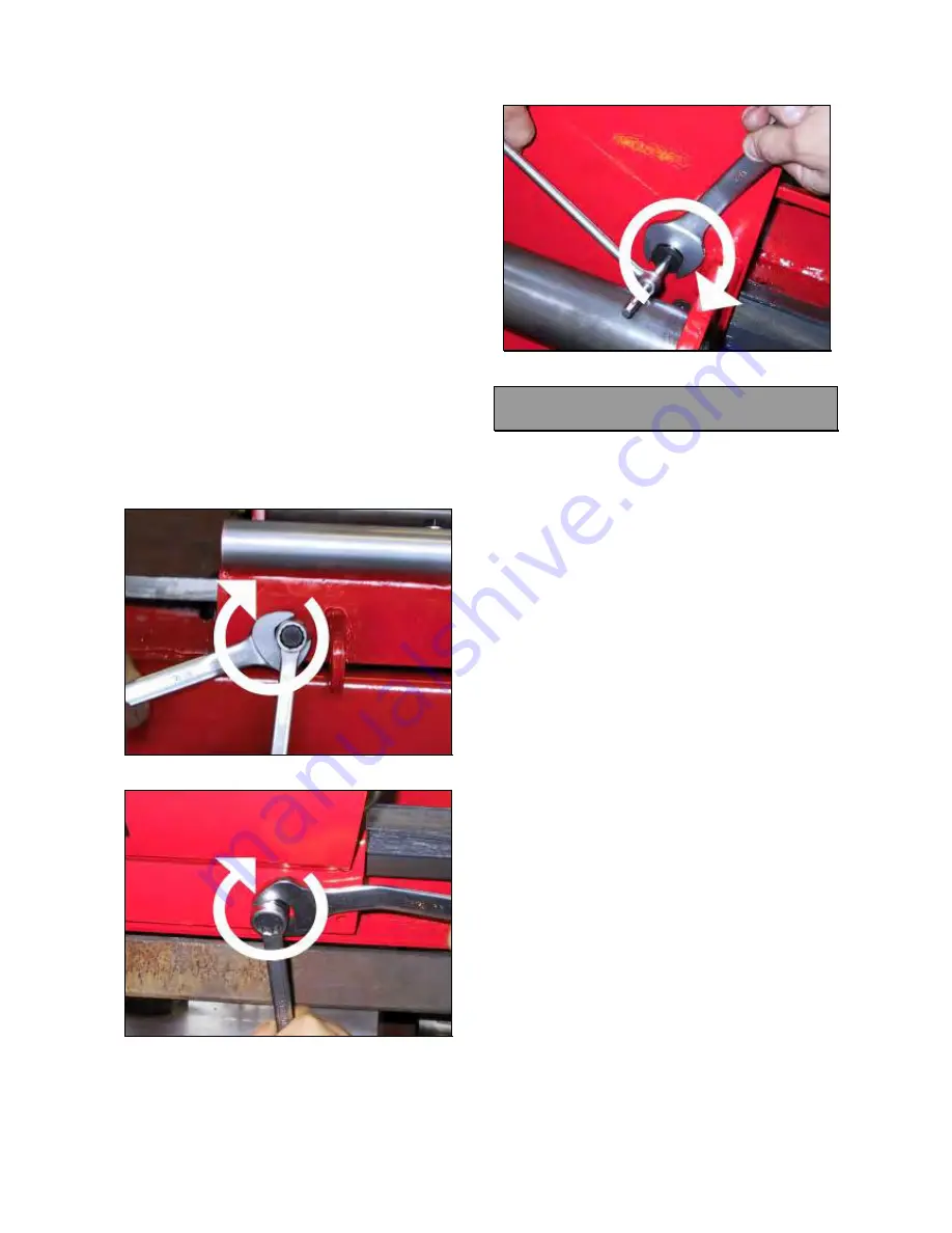
(Fig.231),(Fig.232 and 233 for King 5600R
only).
Fig.231
Fig.232
Fig.233
7.2 KING 5600R SADDLE SLIDES:
CHECK AND REPLACEMENT
:
4h
:
End wrenches 10,13,17,19, 22, 24mm, allen
wrench of 4,5 and 6mm, socket wrenches 17
and 22mm, 13mm tube type wrench,
manometer, rubber hammer, Wrench
adjustment of saddle clearance, Tool for
removal of cylinder pin
L
:
Broken or worn saddle slides may cause the
following malfunctions:
1. The eccentrics make a complete turn without
tighten the saddle.
2. Excess of saddle play.
3. Incorrect distance between tool and rim.
TO CHECK THE SLIDES:
To check the saddle sliding pressure
6.6.
If the pressure shown by the manometer is
always lower than 30 bar (430 psi)
7.1
If the eccentrics make a complete turn without
tighten the saddle the slides need to be
replaced.
TO REPLACE THE SLIDES:
Turn the machine on and close the saddle
cylinder ‘till end of stroke.
Lift up the hook (Fig.220).
Turn the machine off.
Remove the mobile plate from the saddle
6.6
Remove the mount dismount tool #1 from tool
holder arm (Fig.234).
Summary of Contents for KING 5600
Page 9: ...Service Manual 04 2010 Rev B 9 3 1 ELECTRIC DIAGRAM FOR CE PROVED KING 5600 Fig 16...
Page 10: ...Service Manual 04 2010 Rev B 10 Fig 17...
Page 11: ...Service Manual 04 2010 Rev B 11 Fig 18...
Page 12: ...Service Manual 04 2010 Rev B 12 Fig 19...
Page 13: ...Service Manual 04 2010 Rev B 13 Fig 20...
Page 14: ...Service Manual 04 2010 Rev B 14 Fig 21...
Page 15: ...Service Manual 04 2010 Rev B 15 Fig 22...
Page 16: ...Service Manual 04 2010 Rev B 16 Fig 23...
Page 17: ...Service Manual 04 2010 Rev B 17 3 2 ELECTRIC DIAGRAM FOR KING SUPPLIED AT 200V 3PH 60Hz Fig 24...
Page 18: ...Service Manual 04 2010 Rev B 18 Fig 25...
Page 19: ...Service Manual 04 2010 Rev B 19 Fig 26...
Page 20: ...Service Manual 04 2010 Rev B 20 Fig 27...
Page 21: ...Service Manual 04 2010 Rev B 21 Fig 28...
Page 22: ...Service Manual 04 2010 Rev B 22 Fig 29...
Page 23: ...Service Manual 04 2010 Rev B 23 Fig 30...
Page 24: ...Service Manual 04 2010 Rev B 24 Fig 31...
Page 25: ...Service Manual 04 2010 Rev B 25 3 3 ELECTRIC DIAGRAM FOR CE APPROVED KING 5600R Fig 32...
Page 26: ...Service Manual 04 2010 Rev B 26 Fig 33...
Page 27: ...Service Manual 04 2010 Rev B 27 Fig 34...
Page 28: ...Service Manual 04 2010 Rev B 28 Fig 35...
Page 29: ...Service Manual 04 2010 Rev B 29 Fig 36...
Page 30: ...Service Manual 04 2010 Rev B 30 Fig 37...
Page 31: ...Service Manual 04 2010 Rev B 31 Fig 38...
Page 32: ...Service Manual 04 2010 Rev B 32 Fig 39...
Page 34: ...Service Manual 04 2010 Rev B 34 Fig 41...
Page 35: ...Service Manual 04 2010 Rev B 35 Fig 42...
Page 36: ...Service Manual 04 2010 Rev B 36 Fig 43...
Page 37: ...Service Manual 04 2010 Rev B 37 Fig 44...
Page 38: ...Service Manual 04 2010 Rev B 38 Fig 45...
Page 39: ...Service Manual 04 2010 Rev B 39 Fig 46...
Page 40: ...Service Manual 04 2010 Rev B 40 Fig 47...
Page 41: ...Service Manual 04 2010 Rev B 41 3 5 HYDRAULIC DIAGRAM FOR CE APPROVED KING 5600 Fig 48...
Page 42: ...Service Manual 04 2010 Rev B 42 Fig 49...
Page 43: ...Service Manual 04 2010 Rev B 43 3 6HYDRAULIC DIAGRAM FOR KING 5600 Fig 50...
Page 44: ...Service Manual 04 2010 Rev B 44 Fig 51...
Page 45: ...Service Manual 04 2010 Rev B 45 3 7 HYDRAULIC DIAGRAM FOR CE APPROVED KING 5600R Fig 52...
Page 46: ...Service Manual 04 2010 Rev B 46 Fig 53...
Page 47: ...Service Manual 04 2010 Rev B 47 3 8 HYDRAULIC DIAGRAM FOR MACHINE NON CE KING 5600R Fig 54...
Page 48: ...Service Manual 04 2010 Rev B 48 Fig 55...
Page 138: ...Service Manual 04 2010 Rev B 138 BLANK PAGE...


