background image

Content 

1.OVERVIEW

 ................................................................................................................................................................... 3

2.PRODUCT INTERFACE DESCRIPTION

 .................................................................................................................. 5

3

.

RECORDER DEBUGGING

 ........................................................................................................................................ 5

4.

FUNCTION AND OPERATION INSTRUCTIONS

 ................................................................................................................ 7

4.1


M

AIN 

S

CREEN

 ............................................................................................................................................................... 8 

4.1.1 Power on

 ............................................................................................................................................................ 8 

4.1.2 System Interface

 ................................................................................................................................................ 9 

4.2


M

ONITOR 

I

NTERFACE

 ...................................................................................................................................................... 9 

4.3


I

NPUT 

C

HANNELS

 ......................................................................................................................................................... 11 

4.3.1 Input channels interface introduction ............................................................................................................. 12 
4.3.2 Input Channel setting ...................................................................................................................................... 13 

4.4


C

AMERA CONTROL

 ....................................................................................................................................................... 17 

4.5


M

EETING 

G

ROUP 

C

ONTROL

(MGT


C

ONTROL

) ................................................................................................................... 18 

4.6


D

IRECTOR FUNCTION

 .................................................................................................................................................... 21 

4.6.1 Interface .......................................................................................................................................................... 21 
4.6.2 Split-screen Processing .................................................................................................................................... 22 
4.6.3 Subtitle and sound ........................................................................................................................................... 23 
4.6.4 logo/OSD information/time setting/additional OSD ....................................................................................... 24 
4.6.5 Insert titles/Insert endings .............................................................................................................................. 25 
4.6.6 Full Auto/Semi Auto/Manual direction ........................................................................................................... 26 

4.7


S

YSTEM FUNCTION

 ....................................................................................................................................................... 26 

4.7.1 Recording control ............................................................................................................................................ 27 
4.7.2 Interact button ................................................................................................................................................ 28 
4.7.3 Quick Start ....................................................................................................................................................... 28 
4.7.4 Simple .............................................................................................................................................................. 29 
4.7.5 System Setting; ................................................................................................................................................ 29 

4.7.6 System Setting

 ................................................................................................................................................. 39 

4.7.7 File management ............................................................................................................................................. 48 

5 NETWORK GROUP .......................................................................................................................................................... 50 

Summary of Contents for AH8201

Page 1: ...AH8201 AH8301 AH854K P Pr ro of fe es ss si io on na al lC Co on nf fe er re en nc ce er re ec co or rd de er r U Us se er r M Ma an nu ua al l V Ve er rs si io on n 1 1 0 0...

Page 2: ...About the Manual Type No Product Versions V1 0 Edited by Pairote Sirichainarumit Updated Date 2019 4...

Page 3: ...MERA CONTROL 17 4 5 MEETING GROUP CONTROL MGT CONTROL 18 4 6 DIRECTOR FUNCTION 21 4 6 1 Interface 21 4 6 2 Split screen Processing 22 4 6 3 Subtitle and sound 23 4 6 4 logo OSD information time settin...

Page 4: ...ware architecture design with highly Supports simultaneous recording and live broadcast of the movie mode resource mode The picture supports picture in picture 1 2 3 4 6 split screen mode display and...

Page 5: ...64 High Profile H 265 AH854K only Recording file format MP4 Video coding frame rate 1 30fps Video code rate 50kbps 40Mbps adjustable Audio code rate 8KB 420KB adjustable Storage Built in 1TB hard disk...

Page 6: ...PGM software can be set 6 HDMI OUT 1 HDMI signal output output screen is the guide interface or PGM software can be set 7 HDMI IN 1 5 HDMI signal input support 2 3 5 channels depend on model 8 LINE I...

Page 7: ...corresponding audio and video input and output connections 2 After confirming that the recording host is properly connected to the power supply then press the power switch of the navigation panel to...

Page 8: ...stem configuration 1 Monitor Interface program in film mode preview or broadcasting PGM PGM2 PVW 2 Video Channel display the input video 3 Camera control to control the camera manually 4 Program panel...

Page 9: ...igure 3 Function Structure 4 1 Main Screen 4 1 1 Power on Press the power button on front panel to power on the system The display connecting to HDMI OUT 1 and monitor on controller will show the boot...

Page 10: ...1 2 System Interface After around 20 seconds you will see the main system interface Figure 9 Main Screen 4 2 Monitor Interface Including 1 PGM and PVW in Movie mode 2 PGM and PGM2 in Res mode 3 Audio...

Page 11: ...e director and Dual director is in the Full Auto mode only supports PGM channel image automatically switch When directing under Dual director mode and Manual mode it could manually switch the output d...

Page 12: ...l 6 screen image is replaced PVW and PGM PGM2 are all support multi screen combination If working under Full Auto you double click the PVM screen only make you get the full screen image Procedure Afte...

Page 13: ...ort 1 and port 2 of local recorder If model AH8301 and AH854K then more HDMI inputs are available and so forth 4 3 1 Input channels interface introduction 1 Full Screen Each input channel display a fu...

Page 14: ...le mp4 click apply and OK Back to the input channel interface click the to play the video and to stop playing The local replay image also can be switch to the PGM channel to live broadcast 4 3 2 Input...

Page 15: ...t channel and can be changed the name according to the source for easily identification 4 Auto Switch Select the Auto Switch ID for the current channel and it work with the switch strategy 5 Disp Mode...

Page 16: ...and RS232 corresponding the RJ45 port 4 Baud Rate support 2400 4800 9600 and set it according to the specification of the camera 5 Address Code The address code should be the same as the camera setti...

Page 17: ...controller to recorder must be corrective 2 The setting of camera protocol baud rate address code input channel under channel input need to be the same as camera 3 Only under the Manual mode the setti...

Page 18: ...stream c ode rate 400Kbps 4 Picture quality level 0 to 5 0 level is the best 5 Frame rate 10 to 30 frame default set is 25 frame 6 GOP time settable default is 30s 4 4 Camera control PTZ control funct...

Page 19: ...he remote audio video to add to the local input channel and display on the local screen Application example 1 conference room as the main conference room and other conference room connect to the main...

Page 20: ...Click the MTG Control Get the interface as...

Page 21: ...eft menu will display the IP of remote recorders You also add the recorder from outside of local network internet by Manual Add Dev button The remote internet recorder need to be mapped its IP to inte...

Page 22: ...nnels Figure 20 Remote channel display As above picture the remote channels are display on the channel no 8 and no 9 on the second page You also can control the audio on the remote channel as the figu...

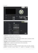
Page 23: ...ng as the figure 22 the PGM PVW and PGM2 can select the types of split screen to display Split screen modes provide 12 types as single screen two screen PIP two screen on corner three screens quad scr...

Page 24: ...view When there is no problem click PGM Insert to publish to the PGM Live screen When the subtitle is inserted into the screen the button will change to Cancel Click on the corresponding PGM Cancel an...

Page 25: ...logo file in the upper right corner of the setting icon You can also customize the image of the angle marking here The standard picture format is png the best The resolution image size of the effect...

Page 26: ...al OSD custom information loaded into the video channel 4 6 5 Insert titles Insert endings Figure 30 Prologue Epilogue setting Choose the path of the video file the format must be mp4 format video fil...

Page 27: ...cking host Note The auto tracking command code must correspond to the tracking of the tracking camera or the tracking master The automatic tracking command code for recording and playing is modified i...

Page 28: ...e left to right is 1 Start recording 2 Pause recording 3 Stop recording 4 Recording time 5 Recording setting Movie Auto Rec Select the auto recording channel after switching on the recorder Files Spli...

Page 29: ...teract button Interact button is launch the MTC Control with another recorder terminal 4 7 3 Quick Start The Quick Start is a shortcut button and set the corresponding parameters at system setting Set...

Page 30: ...e interface for the end user to operate the system and reduce the setting buttons 4 7 5 System Setting The system settings include 4 main menu such as Channel Setting File and User as bellowing figure...

Page 31: ...1 HDMI2 HDMI5 channel Remote Remote interact channel File Channel local video play channel 4 7 5 2 Settings All the setting of the system is available under this menu 4 7 5 3 File Manage the recorded...

Page 32: ...4 7 5 4 User Manage the user to login this system restart and reset the default system etc...

Page 33: ...You can select the audio Codec parameter HDMI OUT is the option to select on or off the sound for the HDMI output If the audio source is microphone and HDMI out connected to a display with speaker it...

Page 34: ...LOCAL PGM Codec Major code Sub code menu to adjust the corresponding stream size Under Movie mode on PGM channel or PGM2 channel to click the RTMP Push button View in the main interface under the Stat...

Page 35: ...reaming port to open and watch the live screen TS multicast using UDP network protocol no user request open the player to watch just tick the corresponding code stream and port number click the TS but...

Page 36: ...and will automatically query switching strategy menu in the strategy table getting the appropriate signal state to switch During the switching some of the effects of switching and screen combination...

Page 37: ...to camera auto tracking controller DCP2000 and the recorder will not response and execute any commands from camera auto tracking controller DCP2000 the camera auto tracking controller DCP2000 is still...

Page 38: ...set channel Note The parameters must be set to copy to a specific date or time recording can t be properly turned on 4 5 7 10 Menu Setting Live Debugging Track Camera Network Setting Figure 50 Track...

Page 39: ...source channel switches to PGM The mouse does not need to activate the PGM channel before and double click the resource channel directly to switch the image to the PGM channel This method quickly swit...

Page 40: ...to download the file from the recorder FTP Download Setting FTP default password is empty just fill in the new password and confirm password two columns 4 7 6 System Setting System setting is included...

Page 41: ...mporarily turned off 4 7 6 2 Menu Setting System Setting Serial Port Setting Figure 54 Serial Port Setting Description As shown in Figure 54 the serial settings menu can be configured to return code t...

Page 42: ...the size If the system required the password the default password is 1 After the disk is full the recorder supports loop coverage or you can select to stop recording The disk formatting file system ha...

Page 43: ...the software upgrade tool under the LAN You can also map the recorder in the LAN to the WAN in the router Mapping 554 port to the external network internet you can use VLC player to play the RTSP rea...

Page 44: ...er to preview the image from the PGM you need to download the FBVLC software https sourceforge net projects fbvlc If you have change the IP address of the recorder you need to change the IP on LIVE SE...

Page 45: ...local area network packet loss and delay data The input IP address must be in the same LAN segment as the IP address of the recorder It is commonly used for network debugging between the RTMP streami...

Page 46: ...card 1 output device from VGA to HDMI graphics card 2 output device from the HDMI to VGA the hardware interface of the VGA signal output is PGM live screen HDMI output signal for the local direction s...

Page 47: ...ct the correct hardware connection interface Support start video pause video stop recording safe shutdown VGA lock and so on a key to open the command code and the central control equipment must be on...

Page 48: ...1024 768 72 dpi bit depth of 24 the file size is not more than 128KB The interface logo picture format is the gif resolution size is 200 100 72dpi bit depth 24 Users can import the logo file into the...

Page 49: ...l hard drive or external storage device with file search delete copy paste and rename commands The Recorder is built in player and the user can double click the xxx mp4 file in the file management men...

Page 50: ...Figure 68 Recording Preview Player...

Page 51: ...and sound and send the standard codes to the network 2 The player which support the codes can receive the codes The recorder will upload the recording files automatically to server the mobile devices...

Page 52: ......

Reviews: