21
7 . I n s t a l l i n g c o n t r o l l e r s , c h a n g i n g p o s i t i o n s , e l e c t r i c a l
c o n n e c t i o n s
7.1.
Installing the controller
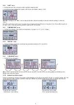
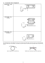
A CPA touch-screen controlled providing full control and programming is connected as standard. It is supplied for installation on
the wall and can be fitted into a recessed installation box.
The controller should be mounted on the wall at a height of 1.3 – 1.5 metres at an easily accessible, well-lit and dry place, not close
to heaters and heat radiating surfaces.
Included is a low-current shielded connecting cable (SYKFY 5x2x0,5) 3 metres long. When the controller is required to be further
away from the ventilation unit, the cable must be replaced / extended (up to 25 metres).The controller must be installed by
a specialized installation company’s technician.
Warning: Before installing or removing the controller disconnect the unit from power supply. Handling the controller with
power left on might lead to electrocuting or damage the controller.
CPA
Installation on the wall
7.2.
Permanent disballancing of supply and exhaust fans
The unit it must be disconnected from power supply before any intervention with!
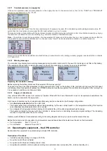
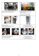
Use the MX terminal block mounted on terminals inside the unit (under the hood, blue accessory on terminals Me and Mi) to
disballance performance of Mi
–
exhaust and Me
–
supply fans.
The disballance can be a maximum of 30 %. Turn
–
adjustment screw is
reduced
performance of the fan – extreme position
= 30% reduction from the original nominal power.
Disconnect the device from the power supply!
Remove the lid of the device
Remove the junction box cover
Rotate
–
to enable the appropriate adjusting screw
for fan or Mi or Me
7.3. Changing the orientation of DUPLEX Easy units
The unit it must be disconnected from power supply before any intervention with!
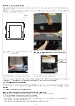
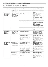
The unit’s orientation is changed simply by changing the production default position of the two temperature sensors and re-
connecting the cables.
T1 – Fresh air intake sensor ( at the filter – red terminals)
T 2 – Exhaust air discharge sensor ( at the M2 fan – blue terminals)
Position of sensors T1 a T2 – default factory position
New positions of sensors T1 a T2 after changing
Summary of Contents for DUPLEX 250 Easy
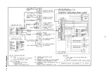
Page 23: ...23 7 4 Wiring diagram ...


