24
7.5.
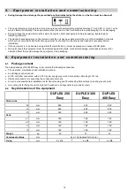
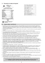
Equipment’s manufacturing label
(1)
Model, nominal capacity
(2)
Manufacturing number
(3)
Year of production
(4)
Weight
(5)
Nominal capacity of fans
(6)
Fan type
(7)
Fan power supply
(8)
Filter class
(9)
Filter cloth dimensions
(10)
Heat recovery exchanger type
(11)
Control system type
8 .
I m p o r ta n t n o t i c e s
DUPLEX series heat recovery units are designed for comfort ventilation in areas with normal environmental conditions and
relative humidity up to 60 %. If the equipment were to be used for other purposes such as to dry out new buildings or not to be
run properly in compliance with instructions contained in the operation and maintenance manual, the manufacturer would not be
liable for any resulting damage.
Only adult persons who have read and are sufficiently familiar with the operation, use and maintenance manual may operate the
equipment.
The user is not allowed to tamper with or modify any part of the equipment, particularly its electrical wiring!!
Only professional service technicians with relevant qualifications may perform equipment repairs. Unprofessional repairs are
very risky and may result in a loss of warranty.
Before opening the door of the equipment for cleaning, filter cloth replacement or general maintenance, make sure that it is
disconnected from power supply and prevent its reconnection by another person.
To prevent injury caused by a fan impeller, ductwork of at least 2 metres in length must always be connected on the fan
discharge side. The ductwork must be fastened to the equipment in such a way that it cannot be removed without tools.
The equipment can only be installed in areas with temperatures up to 10 °C and relative humidity 60 % at 20 °C.
If the equipment has been out of operation for a long period, extra care must be taken during its re-commissioning.
The equipment designed for normal environmental conditions may be operated within the temperature range of ventilation air
between -25 °C and +45 °C and relative air humidity up to 70 %, in an environment where there is no risk of fire or explosion of
flammable gases and fumes, not containing organic solvents or aggressive substances that might damage the mechanical parts
of the equipment. If there is a danger of such gases and fumes temporarily entering the duct system (e.g. floor bonding,
painting), the equipment must be switched off sufficiently beforehand.
Only persons with relevant electrical engineering qualifications may make electrical connections, commissioning and setting of
the equipment.
The units must be protected with a 1 x 10A char. C circuit breaker.
If additional protection against a dangerous touch of live and neutral parts using a current protector is used, a special current
protector designed for circuits with frequency convertors and switched-mode power supplies is necessary. It is a protector
sensitive to alternate, pulse and residual currents and resistant to current surges 5kA.
Before installing and commissioning the equipment, thoroughly read the installation, use and maintenance manual!
The equipment and all accessories must be installed and used in compliance with the design, the technical conditions of the
manufacturer and applicable legislative regulations and technical standards.
The equipment must not be installed and operated in an aggressive environment which could damage its external and internal
components.
Before putting the equipment into permanent operation, an initial inspection report for the equipment’s power supply must be
provided.
In the event of a defect the equipment must be immediately disconnected from power supply!
During the installation and handling of the equipment observe all rules of safe work, including safe work in heights and work with
suspended loads, and use suitable protective equipment.
During installation make sure the equipment’s enclosure does not get damaged or deformed.
The manufacturer is not liable for damage caused by improper installation which fails to observe the
installation manual and common practice in installing HVAC units and control systems.
Summary of Contents for DUPLEX 250 Easy
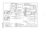
Page 23: ...23 7 4 Wiring diagram ...


