10
V. FRONT PANEL
WARNING! The messages in this section are applicable for equipments having software version Y12C.
If the version changes, the messages and functions will change as well.
5.1 Introduction
The front panel of UPS, consisting of a 2 lines alphanumeric display, 2 status lamps, plus 3 function keys,
allows the complete monitoring of the UPS status. The mimic flow diagram helps to comprehend the
operating status of the UPS. By using the function keys operator can move on menus and change some
parameters.
By-Pass : If lamp is lit static bypass is active and load is connected to mains voltage
Inverter : If lamp is lit inverter supplies the load
There are 3 function keys on front panel these are ENTER, DOWN and (
↔
↔
↔
↔
).
DOWN keys help moving on menus, (
↔
↔
↔
↔
) key selects options, ENTER key means the selected option or
menu is valid.
NOTE : During parameter settings, “+” sign will change into “—“ sign if “
↔
↔
↔
↔
” button is pressed for 3
seconds and the parameter values will start decreasing.
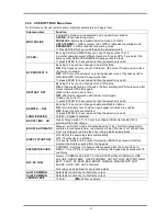
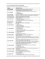
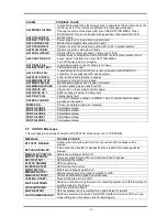
5.2 Front Panel Menu Descriptions
By using menu buttons on the front panel you can move on main menu functions. You can enter the
submenu of the item seen on the LCD panel (MEASURES, ALARMS, INFORMATION) and navigate
within it by using again
and
↵
↵↵
↵
(Enter) buttons.
MEASURES
LOAD ..: %
(output load percentage )
OUTPUT.:000 V
(output voltage )
IPV:000 V
(output frequency )
IPV:000 V
(input voltages )
IPV:000 V
(bypass voltages )
BATTERY: V
(battery voltage and current )
...... etc
ENTER
Figure 5-1
Summary of Contents for HP-115
Page 1: ...USER MANUAL HP 100 SERIES UNINTERRUPTIBLE POWER SUPPLIES 1 Phase Input Output HP 115 NS151A ...
Page 2: ......
Page 4: ......
Page 24: ...20 ...
Page 25: ...21 Connection Diagram Of The RMP COM1 T MON ...
Page 28: ...AGKK8480 06 2009 ...


