background image


A.V.R. operation manual 


15

 -


12.


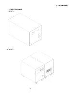
Single Phase Diagram 

2~10KVA 


15~30KVA 


Summary of Contents for PowerMaster

Page 1: ...A V R operation manual 1 PowerMaster Automatic Voltage Regulator User Manual ...

Page 2: ...ement 8 6 Preparation before operation 8 7 Operating procedure 9 8 Treatment for electromagnetic switch jumped 10 9 Specification 10 10 Calculation to Capacity 11 11 output Voltage and Delay Adjustment 12 12 Line Connection Diagram 13 13 Single Phase Interior Diagram 14 14 Notes for Power Distribution 17 15 Power Polarity Judging Method 17 16 Troubleshooting 18 ...

Page 3: ...c shock do not remove cover No user serviceable parts inside refer servicing to qualified service personnel 2 Product inspection Each Automatic Voltage Regulator has passed through the most stringent quality control tests at the factory When the Automatic Voltage Regulator arrives at the customer s site please immediately check the following 1 Do the model capacity voltage setting and serial numbe...

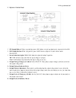
Page 4: ...s that the input voltage is too low 4 Output Voltage Changeover Switch Each of the R S T three phases output voltages can be measured on the output voltage meter 5 Output Voltage Indicator Meter 6 Output Voltage Adjustment This point is used for adjusting the output voltage meter to zero when the mains input power supply is turned off and the output voltage meter does not indicate to zero you must...

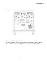
Page 5: ... there are two switches needed to change over simultaneously then the right one is through the automatic voltage regulator and the left one is not and after the master power supply switch is pressed on then successively to press the ON power supply switch on the panel 3 Input electrical connection terminal three or four points referred to connection diagram 4 Output electrical connection terminal ...

Page 6: ...lectric control circuit board R S T three pieces 6 Overload protection fuse R S T three pieces provided only for machine model number more than 20K 7 Bypass over high voltage protection switch provide only for machine model number than 45K ...

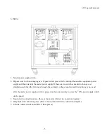
Page 7: ...ge over simultaneously then the left one is through the automatic voltage regulator and the right one is not and after the master power supply switch is pressed on then successively to press the ON power supply switch on the panel 3 Input electric connection place three or four points referred to connection diagram 4 Output electric connection place three or four points referred to connection diag...

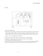
Page 8: ... power supply switch is pressed on then successively to press the ON power supply switch on the panel 3 Input electric connection place three or four points referred to connection diagram 4 Output electric connection place three or four points referred to connection diagram 5 Electric control circuit board R S T three pieces 6 Overload protection fuse R S T three pieces provided only for machine m...

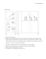
Page 9: ...he automatic voltage regulator and downward does not and after the master power supply switch is pressed on then successively to press the ON power supply switch on the panel 3 Input electric connection place three or four points referred to connection diagram 4 Output electric connection place three or four points referred to connection diagram 5 Electric control circuit board R S T three pieces ...

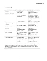
Page 10: ...rticles on the top of the regulator on which there is provided with ventilating holes 6 Preparation before operation 1 Before operation please check the following inputted industrial current values Is Voltage right Is phase number right Is grounded line right 2 When those values are right still not operating the automatic voltage regulator till all output terminals of installation such as computer...

Page 11: ...A V R machine model less than 75K do not continuously operate for more than 48 hours 2 When industrial current is abnormal When the industrial current is altered up to more than that of allowed input range and output adjustable range The electromagnetic switch driven by high low voltage circuit will interrupt the output power supply At this time please stop making use of the automatic voltage regu...

Page 12: ...ption power when A V R capacity is selected It is necessary to consider the possibility in future to expand the installation capacity so that A V R capacity may be generally added extra 25 at least Therefore the A V R capacity is A V R practical capacity Total capacity VA 125 For example A computer is operated with voltage 115V and total current 50AMP A V R KVA 115V 50A 1000 125 5 75KVA 125 7 18KV...

Page 13: ...e direction for lowering protection voltage 4 Adjusting over low voltage protection clockwise direction for rising protection voltage and counterclockwise direction for lowering protection voltage 5 and 6 Voltage regulation adjustment delay to insert into a jump line plug for delaying 3 4 sec to start adjustment This may extend the use life of A V R in which environment usually has a high low volt...

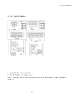
Page 14: ...al 14 12 Line Connection Diagram 1 Input voltage line connection section 2 Output voltage line connecting section Notes 1 when input power is 3Ø3W and output power is 3Ø4W the neutral line of input voltage is not connected ...

Page 15: ...A V R operation manual 15 12 Single Phase Diagram 2 10KVA 15 30KVA ...

Page 16: ...cription 1 Output Voltage Meter 2 Input Output Changeover Switch Right Output Left Input 3 ON indicator 4 AC Input Mains Switch 5 Voltage Adjusting Hole Using a screw driver for adjustment 6 Input Output Terminal 7 Output Outlet Panel Rear Side ...

Page 17: ...g a screw driver for adjustment clockwise direction for rising voltage Power Indicating Light Power Supply upper for turn on and down for turn off Output voltage sensitivity adjustment 1 2 Percentage ON ON 0 8 ON OFF 1 OFF ON 1 4 OFF OFF 2 3 ...

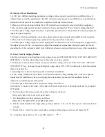
Page 18: ...ection 15 Power Polarity Judging Method 1 Hot Line in respect to hot line line to line voltage there are 190V 200V 208V 220v 230V 380V 400V 415V 440V 480V etc for three phase three lines or three phase four lines systems 2 Neutral line is also called water line in respect to hot line voltage there are 100V 110V 115V 120V 127V 132V 220V 227V etc in inspect to grounding lint voltage about 0 2V 2 0V ...

Page 19: ... new equipment installed Is current meter troubled Please check the load Please renew a A V R with larger capacity Renew a current meter 4 Output voltage higher Is PCB troubled Does output voltage happen to phase lagged Is voltage meter troubled Is VR loose Renew PCB Repair input power supply again Renew a voltage meter Adjust VR to rated value 5 Output voltage lower Is current overloaded Is three...

Reviews: