background image


4

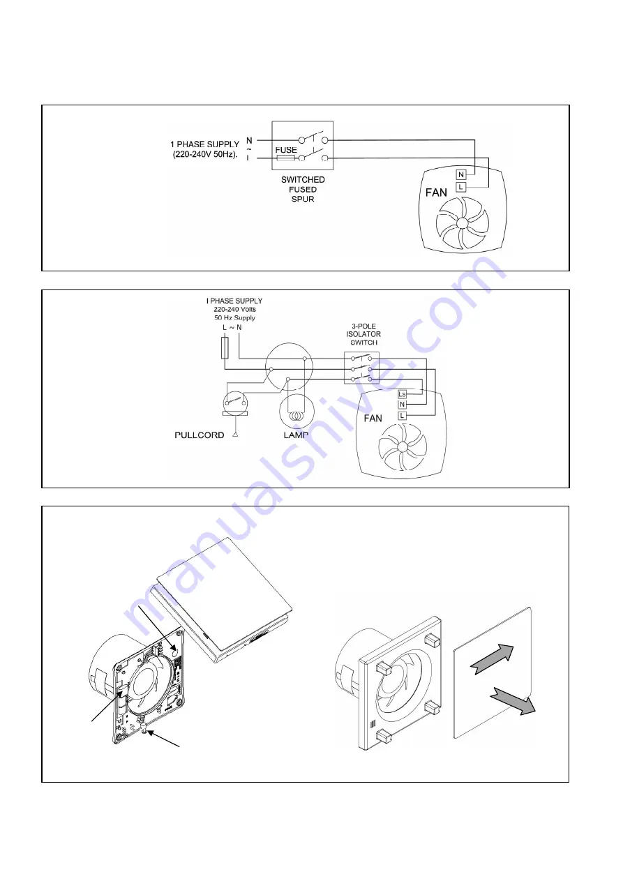
Fig.2 – Basic VASF100B 


Note: LS is not used on the basic model 

Fig.4 – Grille removal for cable entry and control PCB access. 
 

To remove the outer cover slide the 
cover to the right to release the 4 
clips (

1

), then out towards you (

2

). 

To refit the cover, line up the 4 
clips on the rear of the cover and 
slide to the left until you hear a 
“click”. 

1.  Select and follow the appropriate wiring diagram. (Fig. 2 or 3) 
2.  Check all connections have been made correctly and ensure all terminal connections are 

securely fastened. 

3.  Ensure the impeller rotates and is free from obstructions. 


Cover retaining screw 

Fig.3 – Timer VASF100T 


Cable entry 
hole in rear of 
fan housing 

Control 
PCB  
position 

3A (Max) 

3A (Max) 

Summary of Contents for Vent-Axia VASF100B

Page 1: ...stallation and Wiring Instructions Stock Ref N 44 66 58A VASF100B 44 66 59A VASF100T PLEASE READ INSTRUCTIONS IN CONJUNCTION WITH ILLUSTRATIONS PLEASE SAVE THESE INSTRUCTIONS Silent Fan IP44 220 240V 50Hz ...

Page 2: ...liance ensure that the air replacement is adequate for both the fan and the fuel burning appliance G The fan should not be used where it is liable to be subject to direct water spray for prolonged periods of time H Where an excessive amount of moisture is present in the air a condensation trap will need to be installed in the exhaust duct Horizontal ducts should slope away from the fan unit Ducts ...

Page 3: ...rough the holes in the fan back plate Drill plug and screw into position Fix exterior grille into position with the louvers positioned downwards Refer to wiring setup sections Note The grille must comply with the standard requirements of your country to prevent access to the fans impeller The wall kit used in this installation should provide a minimum ducting length of 60mm from the fans back plat...

Page 4: ... cover line up the 4 clips on the rear of the cover and slide to the left until you hear a click 1 Select and follow the appropriate wiring diagram Fig 2 or 3 2 Check all connections have been made correctly and ensure all terminal connections are securely fastened 3 Ensure the impeller rotates and is free from obstructions Cover retaining screw Fig 3 Timer VASF100T Cable entry hole in rear of fan...

Page 5: ...SILENT FAN VASF100T WITH TIMER 1 Low speed Connect N L LS Fig 3 Jumper J1 Factory fitted at low speed Fig 5 2 High speed Connect N L LS Fig 3 Jumper J1 must be moved to select high speed Fig 5 When switched ON the fan will operate at the selected speed and will continue to run for a pre set time after the LS switch is turned OFF TIMER ADJUSTMENT VASF100T ONLY BEFORE ADJUSTING THE TIMER SWITCH OFF ...

Page 6: ...supplier Vent Axia guarantees its products for two years from date of purchase against faulty material or workmanship In the event of any part being found to be defective the product will be repaired or at the Company s option replaced without charge provided that the product Has been installed and used in accordance with the instructions given with each unit Has not been connected to an unsuitabl...

Reviews: