2
6
SW2
P1
SW1
5
GB INSTALLATION
INSTRUCTIONS
MPP/300LR non sarà più possibile
accedere alla programmazione
base dei posti esterni.
Per ripristinare le condizioni di
default vedere capitolo dedicato.
Ripristino condizioni di default dal
posto esterno
1
- Togliere il ponticello SW1.
2
- Chiudere il contatto dell’apriporta
a massa.
Una nota acustica conferma l’avve-
nuta operazione.
3
- Reinserire il ponticello SW1.
Caratteristiche tecniche
• Alimentazione:
12÷16 V ca
14÷18 Vcc.
• Assorbimento:
- a riposo con 14 Vcc 120 mA max;
- attivo con 14 Vcc 150 mA max;
- con elettroserratura attiva aggiun-
gere 500 mA;
- per ogni HEP/306-HEP/312D ag-
giungere 35 mA;
- per 64 derivati interni aggiungere
64 mA.
• Segreto di conversazione audio.
• Comando elettroserratura: di tipo
impulsivo per elettroserratura a 12
V 1 A.
• Tempo attivazione elettroserratura:
regolabile da 1 a 15 s.
• Tempo di attivazione dell’impianto:
60 s.
• Tempo di durata della chiamata: 30 s.
• Uscita bus: alimentazione a 15 Vcc
per amplificatore e derivati interni.
• Uscita comando aux 1: 3,5 Vcc a 1
mA (disponibile solo a posto ester-
no attivo, tempo di attivazione
uguale a quello dell’elettroserratu-
ra).
• Uscita comando aux 2: 3,5 Vcc a 1
mA (sempre disponibile su tutti i
posti esterni, tempo di attivazione
uguale a quello dell’elettroserratu-
ra).
• Uscita attivazione posto esterno:
3,5 Vcc a 1 mA (attivo per tutto il
tempo della comunicazione).
• Temperatura di funzionamento: da
-15 °C a +50 °C.
Istruzioni per l’installazione
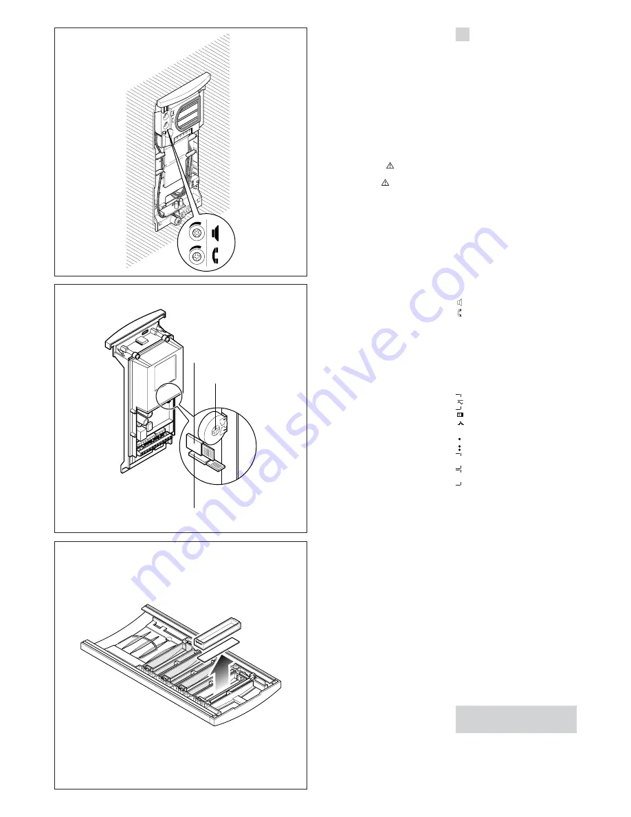
La scatola incasso va murata a filo
muro e ad un’altezza adeguata.
Nella messa in opera della scatola
incasso saranno evitate possibili
deformazioni utilizzando l’apposito
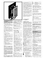
distanziale in dotazione (fig. 1).
Tramite la chiave maschio esagonale
s 2,5 in dotazione svitare la vite di
bloccaggio e smontare la placca dal
telaio (fig. 2).
ATTENZIONE. I cavi di collegamento
devono essere introdotti attraverso
uno dei punti a rottura prestabilita,
situati nella parte inferiore della sca-
tola incasso (A di fig. 1).
Togliere i due bollini di protezione dei
fori filettati nella scatola incasso e fis-
sare il telaio tramite le due viti in
dotazione (fig. 3).
Per il montaggio di ulteriori pulsanti
seguire le istruzioni in dotazione agli
stessi. Effettuare i collegamenti.
Per scrivere i dati desiderati sul car-
tellino portanome, estrarre il ferma
cartellino e quindi il cartellino (fig. 6).
NOTA.
Si possono utilizzare cartellini
portanome personalizzati fino ad un
massimo di 2 mm di spessore.
Per montare la placca inserire prima
la parte superiore nella testata e
quindi, tramite una chiave maschio
esagonale s 2,5, avvitare la vite di
bloccaggio (fig. 7).
5
21
8
11
12
14
4
AUDIO ENTRY PANEL HEC/301
Single-button audio entry panel for
managing the whole installation.
Teamed with button plates HEP/306-
HEP/312D, installations with up to 64
users can be set up.
For connections to user extensions
the entry panel uses BPT
X2 TECH-
NOLOGY
bus connection, enabling
all signals involved in installation to
be sent along a telephone-type sin-
gle twisted pair line.
An additional three video-entry or
audio-only entry panels can be
added to the first in series without the
need for other equipment (selectors,
distributors).
The entry panel comes ready to
house the KHSO luminous system
busy warning kit and 3 KHPS (or 2
KHPD) call kits.
The entry panel comes complete
with:
- phonic unit;
- infrared LED for lighting the target
area;
- three potentiometers for the fol-
lowing functions (fig. 4-5):
volume control at entry panel;
volume control at receiver;
P1
timed (in the range 1 to 15 s) sole-
noid door-lock release.
The entry panel comes with system
busy and door-lock release buzzer.
The wires supplied make it simple to
connect the entry panel’s various
component units.
Function of each terminal
12÷16 V AC 14÷18 V DC
power supply
solenoid lock output
door-lock release button
–
earth for solenoid lock
auxiliary command 1 output
auxiliary command 2 output
B IN
bus input from other entry
panels
B OUT
bus output towards recei-
vers or other entry panels
Connector functions
5-pin CN1 connector:
used for con-
nection to entry panel HEP/306 or
HEP/312D.
3-pin CN3 connector:
used for con-
nection to buttons KHPS or KHPD.
1-red:
to button n° 2.
2-orange:
to button n° 3.
3-yellow:
to button n° 4.
WARNING. In installations with a num-
ber of entry panels, call buttons must be
arranged in the same order on each.
Connector CN4:
comes ready con-
nected.
1-black:
to button no. 1.
2-brown:
to button no. 1.
3-green:
to LEDs lighting the buttons.
4-yellow:
to LEDs lighting the buttons.
2-pin CN5 connector:
used for connec-
tion to KHSO luminous warning kit.
WARNING. Wires belonging to
cables that are not used must be
insulated.
Function of jumpers SW1 and SW2
(fig. 5)
SW1
: automatic programming of
number of entry panels (default set-
ting 1).
SW2
: programming of receivers.


