background image

© BQT Solutions (SEA) Pte Limited 


             Page 4 

4. PRE - INSTALLATION ASSESMENT 


4.1 Mechanical 


The COBALT-mini is designed for mortise installations as this offers a discrete solution as the lock and strike plate 
can  be  embedded  into  the  door  and  frame.  In  some  instances  however  mortise  installation  is  not  possible  so  by 
utilizing the YD30M housing, surface installation of the COBALT-mini is possible. Whichever installation method is 
chosen it is important that the lock and strike plate are aligned correctly. The strike plate has an opening to accept 
the bolt pin and centring this opening with the bolt pin will ensure correct operation. 
  

The  COBALT-mini  can  be  installed  vertically  or  horizontally  but  is  not  designed  to  be  mounted  in  a  floor 
cavity firing upwards or in a wet environment.


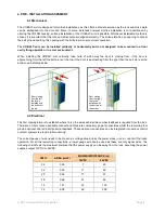
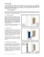
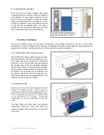
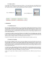
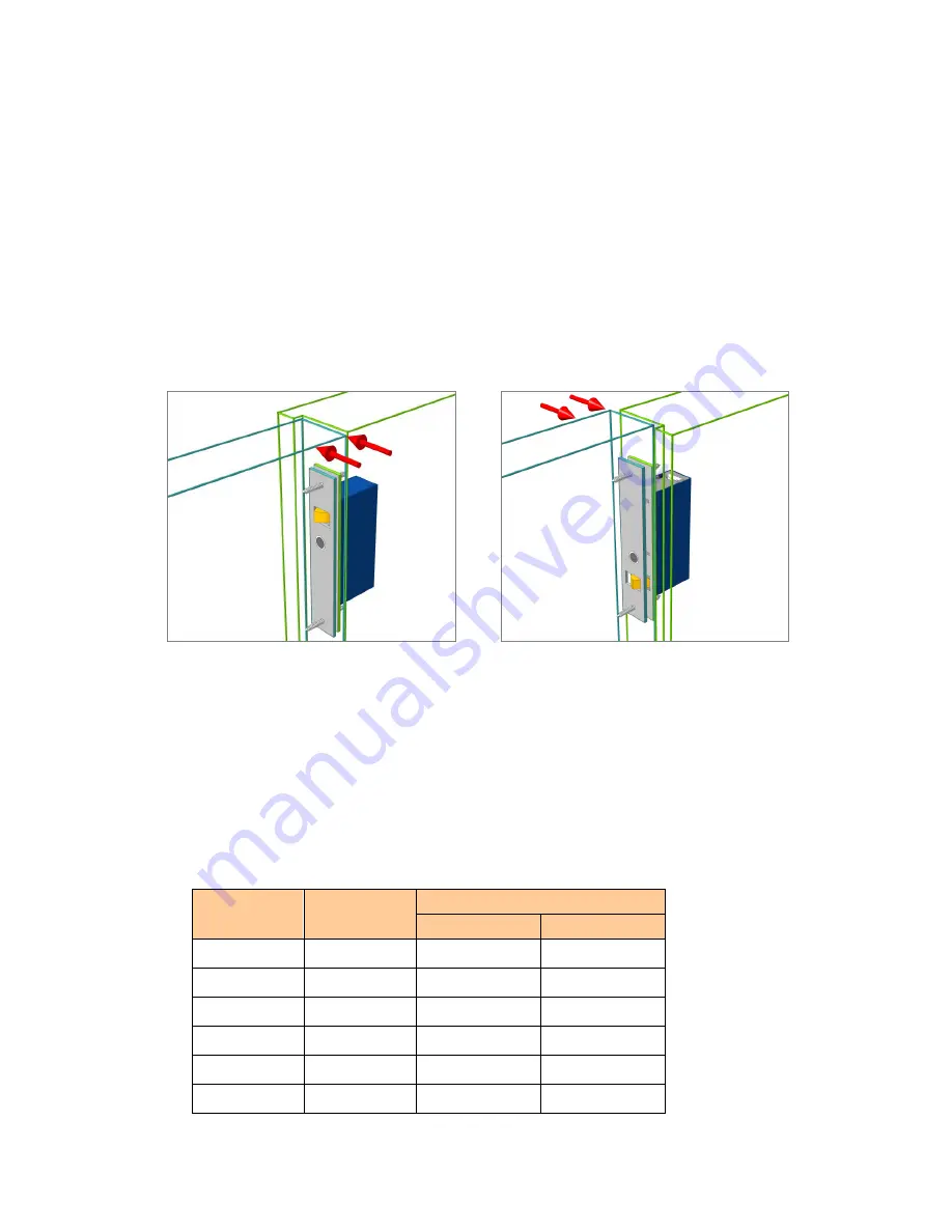
When  installing  the  COBALT-mini  vertically,  take  note  of  which  way  the  door  is  closing  from.  It  the  door  is 
approaching form the left the bolt pin is at the top, if the door is approaching from the right then the bolt pin is at the 
bottom, as indicated below: 


4.2 Electrical 


The first consideration is to establish where to run the wires and decide on what feedback is required from the lock. 
There are a total of seven available connections; three are compulsory power connections whilst the remaining four 
provide optional door and bolt position feedback. These optional connections can be integrated into access control 
or alarm systems to provide full monitoring. 
 
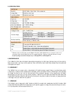
The correct gauge of wire needs to be chosen as voltage drop across the power wires (+ and -) can limit the locks 
operation. For all the remaining connections, a lower gauge wire can be used as these are only signal wires. The 
following chart shows the maximum distance that the power supply can be away from the lock, assuming the power 
supplies output 12VDC or 24VDC: 
 

AWG 

AREA (mm2) 

MAXIMUM DISTANCE (m) 

12VDC 

24VDC 

24 

0.20 

20 

22 

0.33 

11 

32 

20 

0.52 

17 

51 

18 

0.82 

27 

82 

16 

1.31 

43 

130 

14 

2.08 

69 

206 


Door closing 
from the right, 
the lock is 
installed with 
the bolt pin at 
the bottom. 

Door closing 
from the left, 
the lock is 
installed with 
the bolt pin at 
the top. 

Summary of Contents for COBALT-mini YD39M

Page 1: ...YD30M COBALT mini INSTALLATION AND OPERATING INSTRUCTIONS...

Page 2: ...T o 4 1 Mechanical o 4 2 Electrical 5 INSTALLATION o 5 1 Mortise Installation o 5 2 Surface installation 6 WIRING o 6 1 Fail Safe connection o 6 2 Fail Secure connection o 6 3 Jumper position 7 OPERAT...

Page 3: ...sition With the door secured and locked the COBALT mini can be given an unlock signal and it will instantly unlock If the door is loaded pre load when the unlock signal is given the COBALT mini will s...

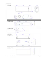
Page 4: ...BQT Solutions SEA Pte Limited Page 3 3 DIMENSIONS 3 1 Lock 3 2 Strike Plate 3 3 Fitting Tab 3 4 Housing Available separately 3 5 Dress Plate Available separately...

Page 5: ...e door is approaching from the right then the bolt pin is at the bottom as indicated below 4 2 Electrical The first consideration is to establish where to run the wires and decide on what feedback is...

Page 6: ...the supplied fitting tabs can be used to secure the lock and strike plate in place The mortise behind the lock body needs to have enough space to accommodate the wiring 5 1 2 Wiring the lock Wires ar...

Page 7: ...determine exactly where the wiring will enter the housing and drill one or two 8mm holes through the housing wall Ensure the holes are on the housing face that goes against the wooden frame Push the...

Page 8: ...glass to give a clean finish The protective coating on the dress plate can be removed once it is in place 5 2 5 Fitting the strike plate into the housing The strike plate is placed into the housing a...

Page 9: ...Door Position Switch WHITE COM 6 1 Fail Safe Connection When wiring the COBALT mini the positive voltage is connected to RED negative is connected to BLACK and a switched positive voltage wire connec...

Page 10: ...ng as the door is open but will instantly re lock when voltage is applied to the BLUE wire and the door is closed In the event of a power failure voltage is removed from the BLUE wire and the COBALT m...

Page 11: ...t after initial power up is 250mA 12VDC and 200mA 24VDC 9 MAINTENANCE The COBALT mini has been lubricated at assembly and applying any other type of lubricant may void the warranty Removing the lock c...

Page 12: ...BQT Solutions SEA Pte Limited Page 11 NOTES Version 3 0...

Reviews: