background image

© BQT Solutions (SEA) Pte Limited 


             Page 6 

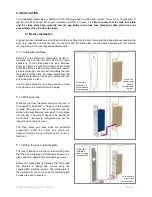
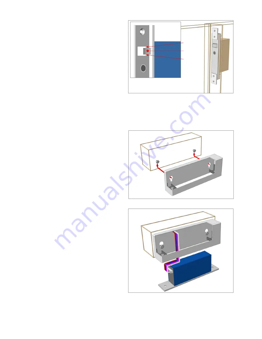
5.1.4 Checking the operation


With  the  lock  and  strike  installed  and  wiring 
complete the door is closed to check the alignment 
and  operation.  The  key  area  for  alignment  is  the 
bolt  pin;  the  pin  is  designed  to  touch  the  leading 
edge of the strike plate hole to pull the door in, but 
it cannot be allowed to touch the sides of the hole 
as  this  will  limit  its  unlocking  ability.  If  its  rubs  or 
touches the side of the strike plate hole, either the 
lock or strike plate needs to be re-positioned.  


5.2 Surface Installation


By  using  a  YD30M  housing,  the  lock  and  or  strike  plate  can  be  surface  mounted  to  the  door  or  door  frame 
eliminating the need for cutting mortises. Housings are available with adhesive tape supplied for easy application to 
glass doors in addition to having screw hole mounting points for wood and metal doors. 

 
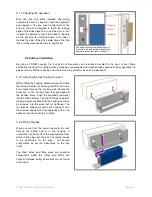
5.2.1 Securing the lock housing to wood 
 

Before fitting the housing, determine exactly where 
the wiring will enter the housing and drill one or two 
8mm  holes  through  the  housing  wall.  Ensure  the 
holes  are  on  the  housing  face  that  goes  against 
the  wooden  frame.  Push  the  supplied  grommet(s) 
into the drilled hole(s). The two 10G Hex head self-
tapping screws supplied with the housing can then 
be  screwed  into  the  wood  but  not  tightened.  The 
two keyhole shaped cut outs in the housing fit over 
these screw heads which are tightened with a ring 
spanner once the housing is in place. 


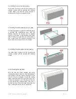
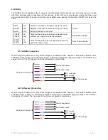
5.2.2 Wiring the lock 

 
Wires  are  run  from  the  power  supply  to  the  lock 
through  the  drilled  hole(s)  in  the  housing.  A 
connection can be made to the supplied wire loom 
which in turn plugs into the lock. The jumper needs 
to  be  positioned  for  fail  safe  /  fail  secure 
configuration  as  per  the  instructions  on  the  lock 
cover. 
 
The  Red,  Black  and  Blue  wires  are  essential 
connections  whilst  the  Violet  and  White  are 
optional.  Detailed  wiring  instructions  can  be  found 
in 

Section 6.


Clearance   

Bolt pin 

Clearance   

The bolt pin touches the leading edge of 
the strike plate hole but there needs to be 
clearance around the sides of the hole.   

Summary of Contents for COBALT-mini YD39M

Page 1: ...YD30M COBALT mini INSTALLATION AND OPERATING INSTRUCTIONS...

Page 2: ...T o 4 1 Mechanical o 4 2 Electrical 5 INSTALLATION o 5 1 Mortise Installation o 5 2 Surface installation 6 WIRING o 6 1 Fail Safe connection o 6 2 Fail Secure connection o 6 3 Jumper position 7 OPERAT...

Page 3: ...sition With the door secured and locked the COBALT mini can be given an unlock signal and it will instantly unlock If the door is loaded pre load when the unlock signal is given the COBALT mini will s...

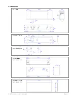
Page 4: ...BQT Solutions SEA Pte Limited Page 3 3 DIMENSIONS 3 1 Lock 3 2 Strike Plate 3 3 Fitting Tab 3 4 Housing Available separately 3 5 Dress Plate Available separately...

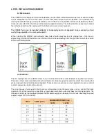
Page 5: ...e door is approaching from the right then the bolt pin is at the bottom as indicated below 4 2 Electrical The first consideration is to establish where to run the wires and decide on what feedback is...

Page 6: ...the supplied fitting tabs can be used to secure the lock and strike plate in place The mortise behind the lock body needs to have enough space to accommodate the wiring 5 1 2 Wiring the lock Wires ar...

Page 7: ...determine exactly where the wiring will enter the housing and drill one or two 8mm holes through the housing wall Ensure the holes are on the housing face that goes against the wooden frame Push the...

Page 8: ...glass to give a clean finish The protective coating on the dress plate can be removed once it is in place 5 2 5 Fitting the strike plate into the housing The strike plate is placed into the housing a...

Page 9: ...Door Position Switch WHITE COM 6 1 Fail Safe Connection When wiring the COBALT mini the positive voltage is connected to RED negative is connected to BLACK and a switched positive voltage wire connec...

Page 10: ...ng as the door is open but will instantly re lock when voltage is applied to the BLUE wire and the door is closed In the event of a power failure voltage is removed from the BLUE wire and the COBALT m...

Page 11: ...t after initial power up is 250mA 12VDC and 200mA 24VDC 9 MAINTENANCE The COBALT mini has been lubricated at assembly and applying any other type of lubricant may void the warranty Removing the lock c...

Page 12: ...BQT Solutions SEA Pte Limited Page 11 NOTES Version 3 0...

Reviews: