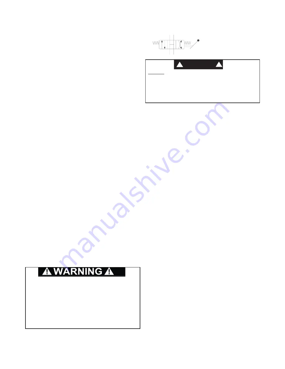
1. The hoist must be mounted with the centerline of the drum
in a horizontal position. The mounting plane can be rotated
to any position around this centerline, providing the vent
plug is positioned above the oil level.
2. When mounting the hoist, we recommend grade eight bolts
and nuts. All mounting holes in the hoist base must be used.
3. The vent plug must always be located above the horizontal
centerline of the hoist drum. If the hoist is mounted on a piv-
oting surface, be sure the vent remains above the centerline
at all times. If necessary, reposition the bearing support.
4. It is important that the hoist be mounted on a surface that will
not flex when the hoist is in use, since this could bind the
working parts of the hoist. Also, be sure the hoist is mount-
ed on a flat surface. If necessary, use shim stock to insure
proper mounting. The mounting surface should be flat with-
in
±
0.020 inches.
5. Hydraulic lines and components that operate the hoist
should be of sufficient size to assure minimum back pres-
sure at the hoist motor ports. Back pressure at full flow rate
should not exceed 100 psi for maximum motor seal life. 150
psi is the maximum allowable peak intermittent back pres-
sure. If high back pressures are encountered, the motor can
be drained directly to tank to improve motor seal life. To
insure adequate static brake load holding ability, back pres-
sure on the hoist should not exceed 150 psi. For pressures
exceeding 150 psi, consult Braden Engineering.
6. Make certain that the hoist drum is centered behind the first
sheave and the fleet angle does not exceed 1½ degrees.
The hoist should also be mounted perpendicular to an
imaginary line from the center of the drum to the first sheave
to ensure even spooling.
7. The hoist directional control valve must be a three-position,
four-way valve
without detents and with a spring centered
motor spool
such that the valve returns to the centered posi-
tion whenever the handle is released, and both work ports
are opened to tank (open center, open port).
8. The hydraulic oil filter should have a 10 micron nominal rat-
ing and be a full-flow type.
9. High quality hydraulic oil is essential for satisfactory perform-
ance and long hydraulic system component life.
Oil having 150 to 330 SUS viscosity at 100°F (38°C) and vis-
cosity index of 100 or greater will give good results under nor-
mal temperature conditions. The use of an oil having a high vis-
cosity index will minimize cold-start trouble and reduce the
length of warm-up periods. A high viscosity index will minimize
changes in viscosity with corresponding changes in tempera-
ture.
Maximum cold weather start-up viscosity should not exceed
5000 SUS with a pour point at least 20°F (11°C) lower than the
minimum temperature.
Under continuous operating conditions the temperature of the
oil at any point in the system must not exceed 180°F (82°C).
120-140°F (49-60°C) is generally considered optimum.
In general terms; for continuous operation at ambient tempera-
tures between 50 and 110°F (10-43°C), use SAE 20W; for con-
tinuous operation between 10 and 90°F (-12 and 32°C), use
SAE 10W; for applications colder than 10°F (-12°C), contact the
BRADEN Product Support Department. The use of multi-vis-
cosity oils is generally not recommended.
8
INSTALLATION
GENERAL REQUIREMENTS
DO NOT
use a control valve with any detents or latching
mechanism that would hold the control valve in an actuat-
ed or running position when the operator releases the con-
trol handle. Use of the wrong type of control valve could
lead to unintentional operation of the hoist, which could
result in property damage, personal injury or death.
!
WARNING
!
Recommended Control
Valve Schematic
The wedge and anchor pocket must be clean and dry.
The end of the wire rope being anchored to the drum
must be clean and dry and not frayed. Anything on the
end of the wire rope to keep it from fraying (i.e. tape or
wire) must not be in contact with the wedge when the
installation is complete. Consult the wire rope manufac-
turer on the proper treatment of the dead end of the wire
rope. Some rope manufacturers recommend when
using rotation resistant wire rope, that the rope end be
seized, welded or brazed before inserting the wire rope
into the wedge socket to prevent core slippage or loss
of rope lay.
Take the free end of the wire rope and insert it through
the small opening on the cable drum. Loop the wire
rope and push the free end about 3/4 of the way back
through the pocket. Install the wedge as shown in fig-
ure 1, then pull the slack out of the wire rope. The
“dead” end of the rope needs to extend slightly beyond
the end of the wedge as shown in figure 2.
WIRE ROPE INSTALLATION -
(ONE PIECE CABLE WEDGE)
THE CABLE ANCHORS ALONE ON HOISTS ARE
NOT DESIGNED TO HOLD RATED LOADS.
Winch
loads applied directly to the wire rope anchor may
cause the wire rope to pull free and result in the sud-
den loss of load control and cause property damage,
personal injury or death. A minimum of 5 wraps of
wire rope must be left on the drum barrel to achieve
rated load.


