9
01 and 02 DRUM – ANCHOR
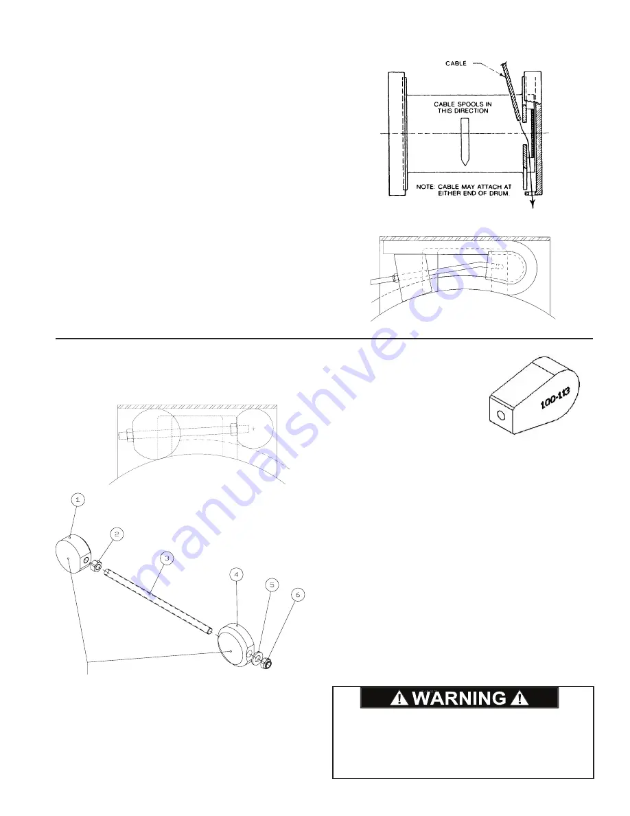
Remove both sheet metal covers from the end bracket of
the winch. Pull the end of the cable through the opening in
the drum flange and out through the end bracket as shown
in Figure 1. Form the cable around part 1 of the wedge as
shown in Figure 2, and pull the assembly into the anchor
pocket (part 2 and the nut are not attached to part 1 at this
time). Access the threaded rod attached to part 1 through
the other opening in the end bracket and install part 2 and
the nut. On large diameter cable, it may be necessary to
hammer on the cable looped around part 1 to force it far
enough into the anchor pocket to attach part 2.
It is important for the dead end of the cable to extend be-
yond the end of part 2, as shown in Figure 2, but not far
enough to come in contact with the end bracket when winch
is operating. A load should be applied to the live end of the
cable to properly seat the anchor. After initial load is ap-
plied, tighten nut holding part 2 in place to 11 ft-lbs. A mini-
mum of five wraps of wire rope should remain on the cable
drum at all times. Refer to General Safety Recommenda-
tions section of this manual for additional information.
3-piece Cable Anchor Installation
(specific to model CH400)
Install threaded rod (Item 3) into Item 1 until it bottoms,
then tighten jam nut (Item 2) against Item 1.
Feed cable through opening in drum flange until it extends
outside cable pocket 2 to 4 inches.
Insert partially assembled anchor (Items 1, 2, 3) into the
cable pocket with flat side of Item 1 against the drum
flange. The anchor will wedge between the cable and the
top of the cable pocket.
Working from the other end of the cable pocket, install
Item 4 onto the threaded rod. Be sure to place the flat side
of Item 4 against the drum flange, then install the rounded
end onto the threaded rod first so the washer (Item 5) and
locknut (Item 6) will seat against the flat end.
Install the washer and locknut onto the threaded rod and
tighten securely to 45 ft-lbs. (This is the torque value of the
1/2-13 stainless-steel rod).
Apply a light load of 1,000 to 2,000 pounds on the cable
and carefully spool it onto the drum. Retighten the nut
again to 45 ft-lbs.
These surfaces face toward
drum flange when installed.
Figure 3
The cable anchor is not designed to hold the rated load
of the hoist. DO NOT apply full rated load until five or
more wraps of cable are on the drum. A sudden loss
of load control could cause property damage, personal
injury, or death.
SPECIAL OFFSHORE BREAKAWAY ANCHOR
NOTE:
Confirm that the cable
clamp assembly is suitable
for your rope size by read-
ing the size range (in inches)
stamped on part itself.
Example
01 AND 02 DRUM – ANCHOR
Remove both sheet metal covers from the end bracket
of the winch. Pull the end of the cable through the
opening in the drum flange and out through the end
bracket as shown in figure 1. Form the cable around
part 1 of the wedge as shown in figure 2, and pull the
assembly into the anchor pocket (part 2 and the nut are
not attached to part 1 at this time). Access the threaded
rod attached to part 1 through the other opening in the
end bracket and install part 2 and the nut. On large
diameter cable, it may be necessary to hammer on the
cable looped around part 1 in order to force it far
enough into the anchor pocket to attach part 2. It is
important for the ‘dead’ end of the cable to extend
beyond the end of part 2, as shown in figure 2, but not
far enough to come in contact with the end bracket
when the winch is operating. A load should be applied
to the ‘live’ end of the cable to properly seat the anchor.
After the initial load is applied, check the tightness of
the nut holding part 2 in place and tighten it if required.
A minimum of five (5) wraps of wire rope should remain
on the cable drum at all times. Refer to “General Safety
Recommendations” for additional information.
–– 7 ––
Figure 1
Figure 2
HYDRAULIC CIRCUITS
SINGLE SPEED CIRCUIT
2 SPEED CIRCUIT
Part
2
Part
1
Summary of Contents for CH330
Page 2: ...2...


