Page 47
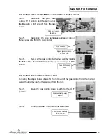
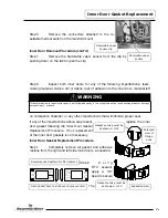
Step 6.
Remove the connectors attached to the re-
settable thermal switch on the manifold mount.
Inner Door Removal Procedure (cont’d)
Step 7.
Remove the flammable vapor sensor from the clip by
pushing down on the tab to open the clip.
Step 8.
Inspect both inner doors for any of the following imperfections: tears,
missing material, cracks, dirt or debris, lack of adhesion to the inner door, material left
on combustion chamber, or any other imperfections that will inhibit a proper seal.
If any of the imperfections above are present,
replace the inner
door gasket following the Inner Door Gasket
Replacement Procedure. If not, replacement
of the inner door gaskets is not necessary.
Inner Door Gasket Replacement Procedure
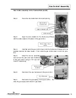
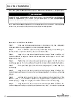
Step 1.
Completely remove all gasket and adhesive
residue from the right and left side inner doors, as needed.
Step 2.
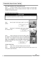
U s i n g
RTV sealant,
apply a 1/8”
bead to secure
t h e
Inner Door Gasket Replacement
Flammable vapor
sensor
Flammable vapor
sensor clip
WARNING
If the information in these instructions is not followed exactly, a fire or explosion may result causing property damage,
personal injury, or death.
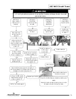
Recommended pattern for RTV sealant
Expanded view
Slice gasket here to slide over burner venturi
Gasket overlap must be
as shown ± 1/32
Enlarged
view of
flange
area
Gasket overlap must be
as shown ± 1/32
47

