Bradley LavCare 500 Series Patient Care Module
Model LC500 L/F and L/W
Installation Instructions
10
Bradley Corporation
215-857 Rev. B; EN 97-1016
Installation Instructions
continued . . .
Step 6b: Install faucet (with foot valve)
and connect water supply
NOTE: On LC500 models with the wristblade
faucet valve, refer to step 6a found on page 9.
On LC500 models with the optional Futura
faucet, use installation instructions specifically
for the Futura faucet when installing the
faucet and making the electrical connections.
NOTE: To make supply connections easier,
remove the access panels first.
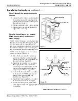
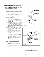
1. Place the faucet onto the countertop, gently
inserting the two faucet supply shanks
through the holes provided in the lavatory
bowl (see Figure 11).
2. Install the two washers provided onto the
supply shanks from beneath the countertop.
Secure the washers and the faucet to the
countertop with the two wingnuts provided
(see Figure 11).
3. Connect one end of the flexible supply
hose provided to the supply shank (see
Figure 11).
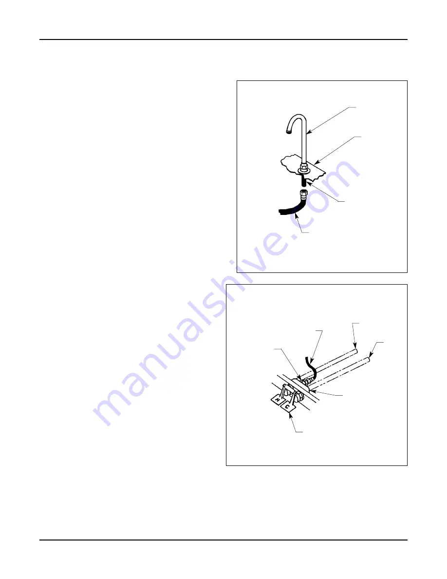
4. Connect the other end of the supply hose
to the foot valve outlet connection (see
Figure 12).
5. Secure the foot valve to the floor using
anchors and bolts (supplied by installer).
6. Connect the hot and cold water supply
(piping supplied by installer) to the 1/2
NPT inlet connectors on the foot valve
(see Figure 12).
Step 7: Complete installation
1. Turn on the water supplies to your
LC500 module and check for leaks.
2. Activate the faucet and flush the valve
several times to purge the air from the
supply lines.
3. Secure the three access panels to the
LC500 with the screws provided.
Figure 11
Figure 12
Installation Instructions
continue . . .
GOOSENECK
SPOUT
LAVATORY
BOWL
SUPPLY
SHANK
SUPPLY
HOSE
SUPPLY
HOSE
FOOT
VALVE
FOOT VALVE
OUTLET
CONNECTION
HOT
INLET
COLD
INLET
FOOT VALVE INLET
CONNECTORS


