
Bradley LavCare 500 Series Patient Care Module
Model LC500 L/F and L/W
Installation Instructions
4
Bradley Corporation
215-857 Rev. B; EN 97-1016
Installation Instructions
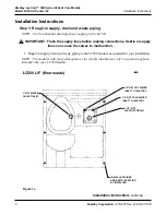
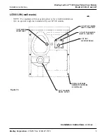
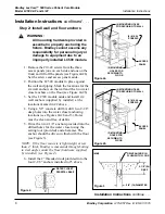
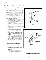
Step 1: Rough-in supply, drain and waste piping
NOTE: Use the submittal drawing when roughing in the LC500.
IMPORTANT: Flush the supply lines before making connections. Debris in supply
lines can cause the valves to malfunction.
1. Rough in supply, drain and waste piping to the LC500 module as required for your installation.
NOTE: For modules with foot pedal option or for retrofit installations, refer to special rough-ins
included with your LC500 module.
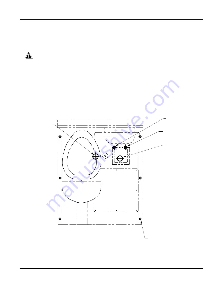
Figure 1a
LC500 L/F (floor waste)
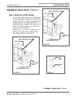
Installation Instructions
continue . . .
1/2 NPT HOT WATER
INLET TO LAVATORY
1/2 NPT COLD WATER
INLET TO LAVATORY
1-1/2 NPT
LAVATORY DRAIN
1 NPT WATER
CLOSET INLET
(6) WALL ANCHORS
AND BOLTS (SUPPLIED
BY INSTALLER
(MM)


