
Bradley LavCare 500 Series Patient Care Module
Model LC500 L/F and L/W
Installation Instructions
6
Bradley Corporation
215-857 Rev. B; EN 97-1016
Installation Instructions
continue . . .
Figure 3
Installation Instructions
continued . . .
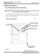
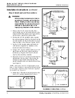
Step 2: Install wall and floor anchors
WARNING:
All mounting hardware provided is
essential in properly anchoring the
fixture. Bradley cannot assume any
responsibility for personal injury or
damage to equipment due to an
improperly installed LC500 module.
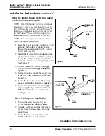
1. Remove the #10-24 screws from the three
access panels (one on each side and one on the
front) and lift off the panels (see Figure 2a/2b).
Set the screws and access panels aside.
2. Position the LC500 module in place against
the wall and piping. Mark the locations for the
six wall anchors on the wall and the two water
closet anchors on the floor (see Figure 2a/2b).
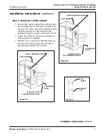
3. Set the LC500 module aside and install six
wall anchors (supplied by installer) at the
locations marked in #2 above.
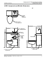
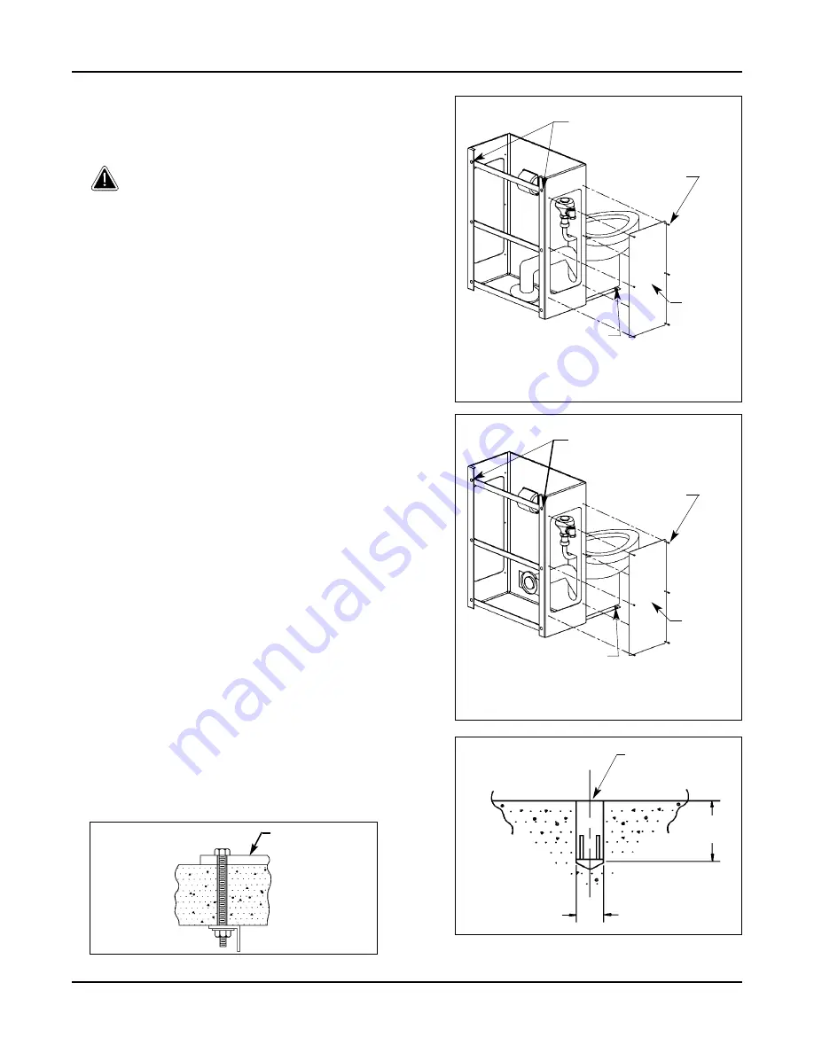
4. Using a 5/8 concrete drill bit, drill two 2-1/8
deep holes into the water closet anchoring
locations (see Figures 2a/2b and 3). Holes
must be clean and free of debris.
5. Drive the two 2-1/8 anchors provided into the
drilled holes for the water closet using the
setting tool (provided) and a hammer. The
anchor should be driven in flush with the floor
(see Figure 3).
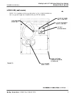
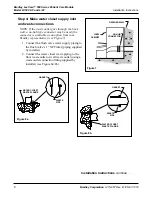
NOTE: If the floor concrete is lightweight or less
than 4 thick, Bradley recommends through-bolting
to steel angles under the floor (hardware supplied
by installer) (see Figure 4).
6. Install the 2 threaded studs provided into the
four 2-1/8 anchors installed in #5 above.
Figure 2a
Figure 4
(6) MOUNTING HOLES
FOR SECURING TO WALL
(6) #10-24
SCREWS
ACCESS
PANEL
(2) MOUNTING
HOLES FOR
SECURING TO
FLOOR
5/8 (16) DIAMETER
DRIVE ANCHOR IN
FLUSH WITH FLOOR
2-1/8 (54)
DEEP
(MM)
WATER CLOSET
PEDESTAL BASE
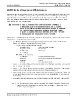
Figure 2b
(6) MOUNTING HOLES
FOR SECURING TO WALL
(6) #10-24
SCREWS
ACCESS
PANEL
(2) MOUNTING
HOLES FOR
SECURING TO
FLOOR


