MF2904/IR
Installation
6
9/25/08
Bradley
Corporation
• 215-752 Rev. U EN 08-023
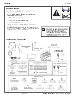
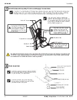
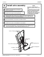
Braided Hose
Cold Supply Inlet
Hot Supply
Inlet
Stop/Check Valve
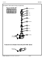
Vernatherm™ TMV
Solenoid Valve Assembly
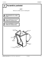
1/4-20 x 1/2" Screws
#10-24 x 3/4" OVAL PHILLIPS
HEAD SCREW
STRAINER
DRAIN SPUD
WASHFOUNTAIN BOWL
SPUD LOCKNUT
(PART OF SPUD)
WASHER (PART OF SPUD)
8
Drain Assembly
Install the optional soap system following
the instructions outlined in manual 215-1136
provided with the soap system.
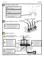
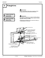
A
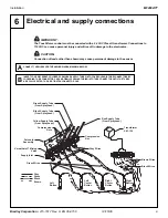
Connect the 1/2" NPT female
end of the stop/check valves
to the rough-ins. Connect
the supply hoses to the stop/
check valves.
7
Install Solenoid Assembly Fixture and Supply Connections
The letter “H" on the Vernatherm™ Mixing Valve indicates hot water supply inlet. The thermostatic mixing valve
requires at least 115° F hot water for proper operation. As with all lavatories, there will be a delay in obtaining
hot water. If the hot water is too far away from the washfountain, a circulating pump may be required.
B
Mount the solenoid assembly
bracket as shown onto the
left side of the pedestal using
the two supplied 1/2-20 X 1/2"
screws. Do not overtighten.
C
Connect the supply hoses
to the Vernatherm™ TMV
valve assembly.
FOR OPTIONAL SINGLE TEMPERED
SUPPLY: Attach the stop/check valve to the
1/2" tempered supply line. Connect the stop/
check valve to the solenoid valve assembly
with the fl exible supply hose.
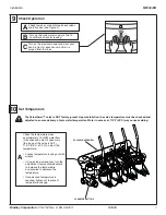
The Adaptive® Infrared control must be connected with a 24 VAC Class II plug-in transformer. Connection with
110 VAC can cause personal injury and will result in damage to the electronics. Consult local electrical codes
and ordinances for suitable transformer mounting location.
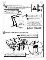
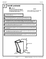
Install drain spud per common industry standard.
(Discard rubber gasket included with drain spud;
it cannot be used in this application.)


