WF2613
Installation
6
3/5/2013
Bradley
•
215-1451 Rev. F; ECN 13-00-001
1
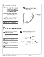
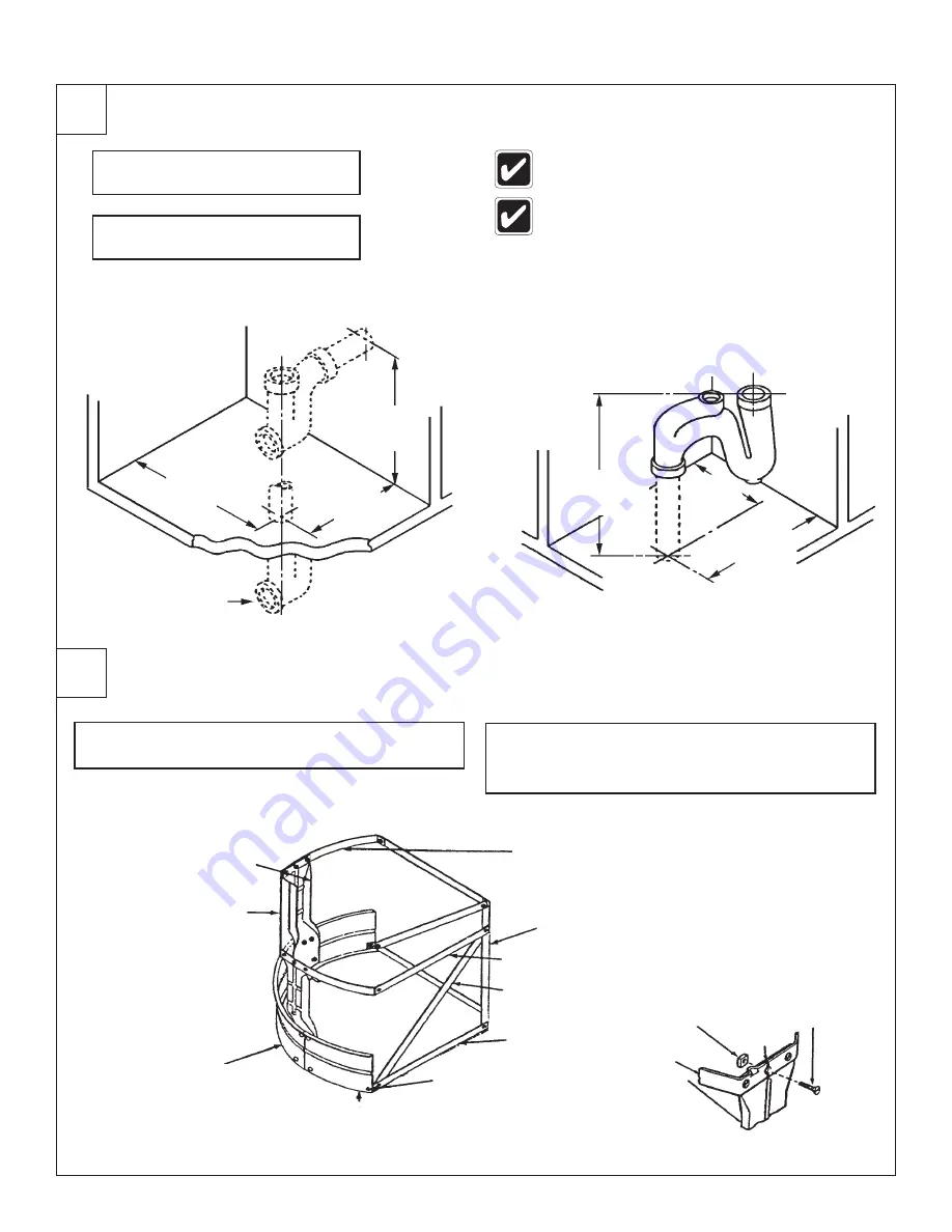
Installing the Drain
A
Rough in supply and drain piping
as required for your installation.
A
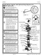
Assemble the legs and scuff base panels with the
5/16" carriage bolts and nuts provided
B
Assemble the drain to the
dimension shown below
B
Attach the pedestal frame members, the rear support
members and the rear legs with the 5/16" stove bolts
and nuts provided.
When an Infrared control is ordered, a plug-in
location for the 24 VAC transformer is required.
Compliance/conformity to local codes and
ordinances is the responsibility of the installer.
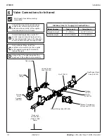
All piping shown in dotted lines
to be supplied by installer.
2
Assembling the Pedestal
Drain Thru Floor
(Optional)
Wall Bracket
(140-146 LH - Left Hand)
(140-146 RH - Right Hand)
Rear Leg
(193-006 Std. Ht.)
(193-006A Juv. Ht. )
Lower Support
(194-041)
Upper Support (194-042)
Diagonal Support
(194-043 Std. Ht.)
(194-043A Std. Ht. )
5/16" Carriage Bolt
(160-060A)
Scuff Base End
(185-023 ALH - Left Hand)
(185-023 ARH - Right Hand)
Scuff Base
(185-015A)
Frame Member
(194-005)
Pedestal Leg
(193-002 Std. Ht.)
(193-002B Juv. Ht.)
12-3/4"
(324)
7-1/4"
(184)
9"
(229)
18-5/8" (473) Std.
14-5/8" (371) Juv.
7-1/4"
(184)
12-3/4"
(324)
Nut
(161-040)
5/16" Flat
Head Stove
Bolt (160-104)
Leg
Frame
Joint
Vented Trap
(111-024)
Type A and O
Type B and H


