Installation
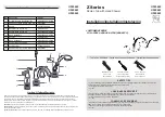
1. If desired, attach mounting bracket to valve mounting posts.
2. Using slots on wall bracket, secure bracket to wall at desired location (screws provided by installer).
3. Connect the hot and cold valve supply inlets to the appropriate hot and cold supply piping. (For S59-4004XS Model, use checkstops and supply
hoses provided connecting supply hoses to valve inlets, and checkstops to opposite end of hose).
4. Connect the mixed valve supply outlet from the valve to the tempered supply piping.
5. Pressurize the thermostatic mixing valve and check for pipe leaks.
NOTE: This valve is
NOT
factory preset. Upon installation, the temperature of this valve must be checked and adjusted to ensure delivery of a safe water
temperature.
Water in excess of 110°F (43°C) may cause scalding.
6. Check the temperature when approximately 1.0 GPM water flow is reached and adjust if
necessary (the range of the valve is 95°F – 115°F (35°C – 46°C). To adjust the temperature, follow the procedure below:
•
Loosen temperature locking nut with wrench.
•
Using a blade screwdriver, turn the adjustment stem
counterclockwise
to
increase
the temperature or
clockwise
to
decrease
the temperature.
•
Once desired temperature is reached, tighten nut to prevent temperature change.
7. Shut the hot water inlet off by closing either the hot water check valve or inlet valve. While the hot water supply is turned off, check to make sure
the cold water flow is reduced. If the cold water is reduced properly, reopen the hot water supply.
8. Shut the cold water inlet off by closing either the cold water check valve or inlet valve. While the cold water supply is off, check to make sure that
the hot water flow has shut down.
3
Installation
S59-4004, S59-4004XS
Bradley
•
9/11/2013
N 13-09-011
E
;
H
.
v
e
R
6
0
5
1
-
5
1
2
Maintenance and Troubleshooting
NOTE: Before attempting to troubleshoot the valve or disassemble the components, check for the following conditions:
•
If stop/check valves are used, make sure that they are fully open
•
Make sure that the hot and cold inlet pipes are connected properly, and that there are no cross-connections or leaking stop/check valves
•
Check the hot water heater output to make sure that it is at least 20°F (-6.7°C) above the set temperature.
Be sure to close the appropriate shut-off valves prior to disassembly of the valve and reopen the valves after inspection and repair is complete.
Problem: Limited water flow
Cause: Dirt and debris have built up in the valve or strainer.
1. Remove and clean strainer. If strainer needs to be replaced, order Bradley strainer 173-028.
2. Check the piston for smooth movement.
To check the valve’s piston for free and smooth movement, follow the procedures outlined below:
1. Remove the valve’s cap and thermostat.
2. Push down on the piston with your finger (the piston should move freely). If the movement is not as it should be, the piston needs to be cleaned.
Follow the method outlined below for cleaning the piston and valve body:
•
Remove the thermostat.
•
Lift the piston out with a needle-nose pliers and remove the spring.
•
Any cleaner suitable for brass and stainless steel may be used (if cleaning with suitable cleaner is not sufficient to remove debris, a 400-grit
sandpaper may be used to polish and hone the piston and valve body).
•
Snap spring into piston (will detent) and reassemble into the valve body.
•
Retest the piston.
3. If, after a thorough cleaning, the piston does not move freely, the piston must be replaced. Contact your Bradley representative and ask for Repair
Kit S65-259.
Problem: External leaks in the system
Cause: O-rings have been damaged.
Solution: Replace O-rings where necessary. For replacement of the O-rings, contact your Bradley representative and ask for Repair Kit S65-259.
Problem: Improper water temperature or temperature fluctuation
Cause: Thermostat is slowly failing or not working at all.
Solution: Check the thermostat for proper operation.
1. At room temperature (80°F [26.7°C] or less) remove cap and thermostat.
2. Place thermostat into container with 115°F (46°C) water. The pushrod should pop out of the thermostat approximately 1/10".
3. If thermostat pushrod does not pop out, the thermostat must be replaced. Contact your Bradley representative and ask for Repair Kit S65-259.
Cause: Valve temperature is not properly set.
Solution: Adjust the temperature per Step 6 of Installation.
Supplies recommended:
•
Shut-off on the outlet if tempered water is supplied to a remote
location
•
Shut-off on the inlets/supplies
•
(2) #10 fasteners (and wall anchors, if necessary) for wall bracket
Tools required:
•
Adjustable wrench (for cap removal) and to loosen locking nut
•
Needle-nose pliers (for piston removal)
•
Blade screwdriver (for temperature adjustment)
OBSOLETE


