background image

 BradyJet J4000 User Manual

21

Sensor Mode Types

Setting the Supply Sensor Mode

Setting the Supply Sensor Mode

The supply sensor mode refers to the method the printer will use to detect the print starting position for 

each label. To adjust the supply sensor mode, open the Brady PrintHub. In most cases you will not 

need to change this setting. By default it is set to sense standard die-cut supply. It is only necessary to 

change this setting if you are using clear labels or any label with a black sensing mark on the back.

IMPORTANT!

Set the supply sensor mode 

before

 loading supply.

1. Connect the printer to the computer using the USB cable. 

Note: 

The mode setting is stored in the printer's internal memory so you will not be able to access 

it unless the printer is turned on and properly communicating with the computer.

2. Open Brady PrintHub on the computer.
3. Click on the 

Label Feed

 tab.

4. Select the graphic that most closely corresponds to the supply you intend to install.

This will initiate the supply sensor mode.

5. Load the supply.

Sensor Mode Types

There are three sensor modes:

Continuous

. (Sensor off) For continuous supply with no die-cut, reflective mark, or holes, set the 

sensor type to Continuous which will turn off the supply sensor. In this mode there is no way to set the 

print starting position. The printer will simply start printing the first label and print each subsequent 

label immediately after that previous one. To produce a gap between prints simply add the desired 

amount of white space to the end of the label being printed.

Reflective

. Use this mode for supply that has a pre-printed black line (black mark) on the back of the 

supply, which indicates the break between labels. Black marks are required on clear supply rolls. Black 

marks can also be used for irregular shaped labels, such as circles larger than 4 inches or on any 

supply where the starting print position cannot be sensed using the label itself.

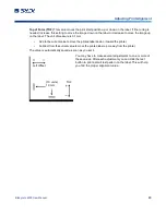
Die-Cut (Default)

. When using standard die-cut labels that look similar to the graphic, use this setting 

regardless of the size of the label. Also use this setting for through-hole label material where a hole is 

punched through each label or a notch is cut in the side.

IMPORTANT!

You must also set the gap sensor position (see 

“Adjusting the Gap Sensor” on 

page 15

) so that the sensor is sensing the correct point on die cut or reflective 

supply. The gap sensor is turned off when set to continuous supply mode.

Summary of Contents for BradyJet J4000

Page 1: ...User Manual...

Page 2: ...assumes no liability arising out of the application or use of any product or system described herein nor any liability for incidental or consequential damages arising from the use of this document Br...

Page 3: ...Y S PART UNDER NO CIRCUMSTANCES WILL BRADY BE LIABLE FOR ANY LOSS DAMAGE EXPENSE OR CONSEQUENTIAL DAMAGES OF ANY KIND ARISING IN CONNECTION WITH THE USE OR INABILITY TO USE BRADY S PRODUCTS Safety and...

Page 4: ...ia bradyid com au technical support Asia Pacific brady co uk landing pages global landing page Registration Information To register your printer go to bradycorp com register Repair and Return If for a...

Page 5: ...Network 10 Installing the Printer Driver 11 Installing Label Supply 11 Installing Ink Cartridges 14 Adjusting the Gap Sensor 15 Circular Label Supply 16 Through hole Supply 16 3 Using System Tools Bra...

Page 6: ...ing from Other Programs 30 5 Maintenance Cleaning the Ink Cartridge Maintenance Station 31 6 Troubleshooting 7 Supply Specifications 8 Regulatory Compliance Agency Compliance and Approvals 38 United S...

Page 7: ...ter has the following specifications Up to 4800 DPI print resolution Draft Mode 4 5 per second Normal Mode 1 8 per second High Quality Mode 0 8 per second print speed Single high capacity Cyan Magenta...

Page 8: ...n prior to setting up or operating the printer Always be sure to adhere to the safety standards regulating your operating environment Also adhere to the following safety rules included in or in additi...

Page 9: ...cal Safety Safety Electrical Safety WARNING Do not remove exterior panels No user serviceable parts inside CAUTION Make sure the power outlet is grounded WARNING To prevent fire or shock hazard do not...

Page 10: ...ter near heat sources such as radiators or air ducts or in a place subject to direct sun light excessive dust mechanical vibration or shock 3 Remove the following additional items from the box USB fla...

Page 11: ...detect the stock When supply is loaded each press of the button will cause one label to be fed through the printer 4 Ink Low LED Illuminates when there is 5 or less ink remaining 5 Unload Button Unloa...

Page 12: ...end labels created with Brady Workstation directly to the printer 2 Network Jack Connect the printer to the network with an Ethernet cable 3 Power Inlet The printer is equipped with a universal power...

Page 13: ...BradyJet J4000 User Manual 7 Registration Internal Parts Internal Parts 1 Fixed Throat Guide 2 Sensor Adjustment 3 Adjustable Throat Guide 4 Roll Stop 5 Roll Guide 6 Roll Arm 1 2 3 4 5 6...

Page 14: ...nal Parts 1 Grit Roller 2 Cutter Track 3 Pressure Rollers 4 Cutter Wheel Access Port 5 Maintenance Station located under Cartridge Carrier 6 Cartridge Carrier Houses the ink cartridge 7 Supply Access...

Page 15: ...ation software provides a variety of apps to simplify label creation for specific purposes It also provides easy to use apps for custom label design The printer comes with a license for the Brady Work...

Page 16: ...the printer in Windows to update the IP address To configure network settings on the printer 1 Make sure the printer is turned on 2 Connect an Ethernet cable not provided to the back of the printer a...

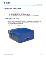
Page 17: ...o the printer driver folder and double click on it 3 Double click on the printer driver executable file and follow the on screen instructions Installing Label Supply Brady labels come equipped with sm...

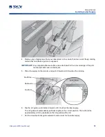
Page 18: ...ner workings of the print mechanism and cause a media jam 5 Place the supply on the roll arm and push it inward until it touches the roll stop 6 Flip the roll guide up and slide it inward until it tou...

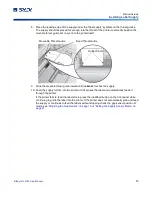
Page 19: ...touches the supply 10 Feed the supply further into the printer until it senses the label and automatically feeds it through the printer If the printer fails to feed the label stock press the load fee...

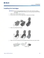
Page 20: ...tridge Pressing the load feed button will allow you to continue printing but will turn off the low ink light 1 Open the cover using the handle on the side 2 Press the tab on the front of the cartridge...

Page 21: ...ition of the gap sensor The sensor can be adjusted using the slide bar on the inside of the printer Below the slide bar is a measurement which represents the distance between the edge of the supply an...

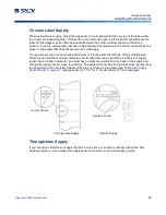
Page 22: ...2 inches from the left side of the printable area Which means that the maximum diameter circular label that can be printed is 4 inches For supply larger than 4 inches in diameter you must have a blac...

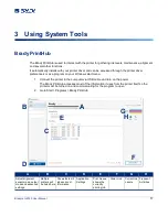
Page 23: ...nect the printer to the computer via USB cable and turn on the power The Brady PrintHub accesses most of the information it uses from the printer itself so the printer must be turned on and communicat...

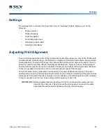
Page 24: ...et J4000 printer however senses the beginning of the label with an optical sensor and is capable of printing to top bottom left and right edge Because of this it is necessary to align the printer to w...

Page 25: ...om the current value to move the tear point away from the printer The value is automatically saved as soon as you set it Left Margin Offset This value moves the printed label left or right Add to the...

Page 26: ...sure is 0 1mm Add to the current value to move the printed label down or toward the printer Subtract from the current value to move the printed label up or away from the printer The value is automatic...

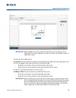
Page 27: ...nuous supply with no die cut reflective mark or holes set the sensor type to Continuous which will turn off the supply sensor In this mode there is no way to set the print starting position The printe...

Page 28: ...n the printer Only use this option if a label rewinder is attached Present after no activity This setting will feed all printed labels past the tear off point at the end of a print job if the printer...

Page 29: ...BradyJet J4000 User Manual 23 Cut Options Viewing Printer Settings Viewing Printer Settings View driver firmware version serial number and software version under this tab...

Page 30: ...if you suspect a cartridge nozzle has become slightly dried out or clogged If the cartridge has been left out of the printer more than 30 minutes the ink in the printhead nozzles may have dried 1 Con...

Page 31: ...o see a printable saveable report click on the document icon next to the job you want to see A report will display the information You can print or save the report from this screen You can also change...

Page 32: ...nged via the method below will apply to all new designs created in Brady Workstation or other programs after the preferences are changed Existing labels saved in Brady Workstation will not be affected...

Page 33: ...image a few millimeters larger than the label by dragging the image over the edge of the label on all sides The bounding box around the image will turn red when it is over the edge of the label Try pr...

Page 34: ...trait and landscape If your text and graphics print left to right or as shown on the screen select portrait If you wish your printing to rotate 90 degrees from what you see on the screen so it is prin...

Page 35: ...olor reproduction is very essential Images printed in this mode will look lighter than those printed in Vivid Graphics mode Skin tones will look more natural in this mode ICC Gloss Paper ICC Gloss Pol...

Page 36: ...Size just as you would set print quality in the printing preferences In the example below the label size is 4 x 4 so the custom page size is set to 400 x 400 displayed in 0 01 inch units 2 Check the i...

Page 37: ...tly press for 30 40 seconds 4 Unfold the second paper towel place on a flat hard surface and press the cartridge nozzle side down on to the top edge of the paper towel 5 Firmly tap the top of the cart...

Page 38: ...r 10 Gently move the cartridge carrier to the left to access the maintenance station The maintenance station is located on the right side of the print area and includes the rubber cartridge nozzle cap...

Page 39: ...increasing the number of extra white space is on the left side of the label or decreasing the number on the right side Refer to Adjusting Print Alignment on page 18 Unwanted white space on the right s...

Page 40: ...ng setting is wrong Change the color matching settings Refer to Print Resolution on page 29 Incorrect label supply is installed Confirm that label supply is ink jet compatible Image mode is incorrect...

Page 41: ...intended printer before ordering large quantities Brady will only assume responsibility for custom label supply ordered from Brady Label Sensing Methods Method 1 Label Gap Sensing Method 2 Through Hol...

Page 42: ...enough to allow the label to be seen by the stock sensor the thickness will only be limited by the printer s ability to pull it through the printer area For these reasons the weight or thickness of th...

Page 43: ...tor to apply your labels be sure to order supply with the correct orientation for your applicator For example most applicators will apply the side of the label first so you will want to print the labe...

Page 44: ...nce that may cause undesired operation Estados Unidos Aviso de la FCC Nota Este equipo se puso a prueba y se confirm que cumple con los l mites para un dispositivo digital de Clase A conforme a la Par...

Page 45: ...f 8 June 2011 on the restriction of the use of certain hazardous substances in electrical and electronic equipment EU Directive 2015 863 of 31 March 2015 amends Annex II to Directive 2011 65 EU of the...

Page 46: ...rdance with the instruction manual may cause harmful interference to radio communications Operation of this equipment in a residential area is likely to cause harmful interference in which case the us...

Page 47: ...io para utilizar el equipo Este dispositivo cumple con la Parte 15 de las Regulaciones de la FCC El uso est sujeto a las siguientes dos condiciones 1 es posible que este dispositivo no provoque interf...

Page 48: ...al y 2 este equipo o dispositivo debe aceptar cualquier interferencia incluyendo la que pueda causar su operaci n no deseada European Union This is a Class A product In a domestic environment this pro...

Reviews: