4
WIRING DIAGRAMS
6
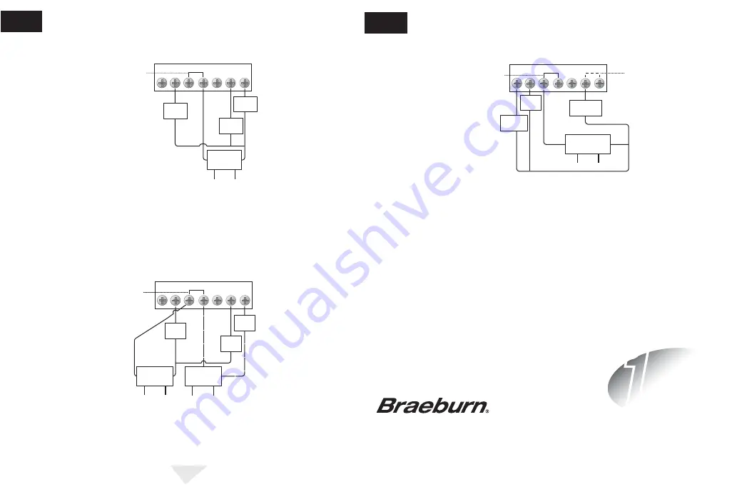
Typical 4-Wire Single Transformer Heating and Cooling System
O
G
W
Factory Installed
Jumper
Y
B
Rc
Rh
Cool
Control
Heat
Control
120
Volt AC
Hot Side
Transformer
24 Volt AC
Transformer
Fan
Control
Typical 5-Wire Two Transformer Heating and Cooling System
O
G
W
Remove
Factory Installed
Jumper
Y
B
Rc
Rh
Cool 24 VAC
Transformer
120
Volt AC
Heat 24 VAC
Transformer
120
Volt AC
Hot Side Cool
Transformer
Heat
Control
Fan
Control
Cool
Control
Hot Side Hea
t
Transformer
NOTES:
1. For Model 505 with Electric Heat, if fan wire is present connect to “W” terminal.
2. For 2-Wire 24 Volt AC or 250mV – 750mV Millivolt Heating Only Systems, remove factory installed jumper.
© 2005 Braeburn Systems LLC • Patents Pending • All Rights Reserved. Pub. No. 500-100-003
Braeburn Systems LLC
2215 Cornell Avenue • Montgomery, IL 60538
Technical Assistance: www.braeburnonline.com
Phone: 866-268-5599
Braeburn Systems LLC warrants each new Braeburn thermostat against any defects that are due to faulty material or workmanship
for a period of one year after the original date of purchase by a professional service technician. This warranty and our liability does not
include damage to merchandise or the thermostat resulting from accident, alteration, neglect, misuse, improper installation or any
other failure to follow Braeburn installation and operating instructions.
Braeburn Systems LLC agrees to repair or replace at its option any Braeburn thermostat under warranty provided it is returned postage
prepaid to our warranty facility in a padded carton within the warranty period, with proof of the original date of purchase and a brief
description of the malfunction. This limited warranty does not include the cost of removal or re-installation. This warranty gives you
specific legal rights and you may also have other rights that vary from state to state or province to province. Answers to any questions
regarding our limited warranty may be obtained by writing our corporate offices.
WARRANTY
YEAR
1
LIMITED
WARRANTY FACILITY:
Braeburn Systems LLC
Attn: Warranty Department
2215 Cornell Avenue
Montgomery, IL 60538
Typical Single Stage Heat Pump Reversing Valve Active in Cooling
O
G
W
Factory Installed
Jumper
Y
B
Rc
Rh
Compressor
Control
24 Volt AC
Transformer
120
Volt AC
Hot Side
Transformer
Fan
Control
Reversing
Valve
See Note 1
cont.
WIRING DIAGRAMS
6
NOTES:
1. Installer must place jumper wire between “W” and “Y” terminals.
2. For Typical Single Stage Heat Pump Reversing Valve Active in Heating, reversing valve
must be connected to “B” terminal instead of “O” terminal.
ONE YEAR LIMITED WARRANTY


