
VM41
VM42
Power consumption, at starting up:
12 VA 15VA
Power consumption, running:
9 VA
12VA
Contact rating:
I max
-Thermostat:
6 A
cos
ϕ
> 0.4
-EV1:
0.5 A
cos
ϕ
> 0.4
-EV2:
0.5 A
cos
ϕ
> 0.4
-Burner motor:
3 A
cos
ϕ
> 0.4
-Alarm:
1 A
cos
ϕ
= 1
-Ignition transformer:
2 A
cos
ϕ
> 0.4
Fuse rating internal:
6.3 A T
Fuse rating external:
5 A F
Flame control:
The ionization flame detecting device makes use of the
rectification property of the flame.
The ionization flame detecting device is not a safe-to-touch
output (no provision with protective impedance).
- Minimum ionization current:
1.2
µ
A
on request:
0.5
µ
A
- Recommended ionization current:
≥
10 times the minimum ionization current
- Minimum insulation resistance of cable and detection
electrode to earth:
≥
50M
Ω
- Max. parasitic capacitance of detection electrode:
≤
1nF
- Max. short circuit current:
< 200
µ
A AC
Weight
including socket:
250g
CONSTRUCTION
A special building technique and the surface mounting
technology for the electronic components have allowed to
realize a box structure and to maintain the dimensions of
the previous mechanical controls unchanged.
The enclosure protects the control from mechanical
damage, dust and dirt from the conditions of installation.
A varistor protects the control from voltage transients on
the mains supply.
A fuse protects the internal relay of the control box in case
of short circuits on the outputs (gas valves, motor,
transformer and lock-out signal). This is not an accessible
fuse and the control must be protected with a fuse of the
fast blow type suitable to the loads connected and never
exceeding 5A.
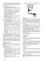
OVERALL DIMENSIONS
Fig. 1 shows the control overall dimensions.
Fig.1
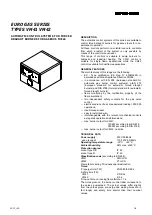
ACCESSORIES
The controls are supplied with inbuilt reset button; the
enclosures are arranged for the fitting of strain relieves
and/or cable holders on the sides (see fig.2).
Fig.2
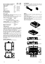
WIRING
The lenght of the cables of external components should not
be longer than 1 m.
For the wiring of the controls you can use connecting
sockets of our production.
Socket N is suitable for the VM41 control, socket NE is
suitable for the VM42 control.
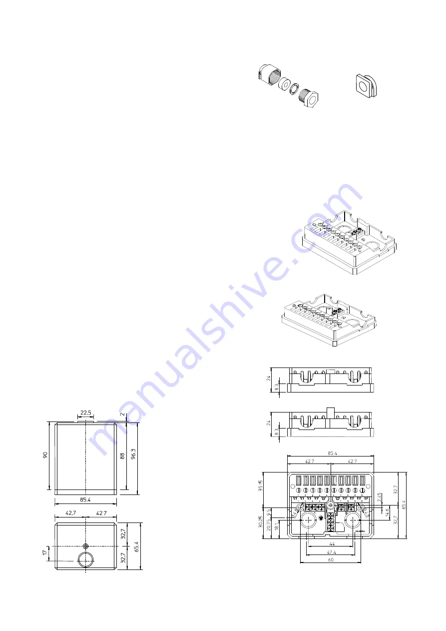
Fig.3 shows these accessories and all relevant dimensions,
useful for the installation.
Socket N
Socket NE
Fig.3
Socket N
Socket NE
2/4 4007_r00


