background image

Technical Manual

Page 3-1

Brand Innovators

Chapter 3

Installation Procedures

3.1

Introduction

This chapter provides the preparation and installation instructions for the BI-0316 module.

3.2

SCSI Bus ID Selection

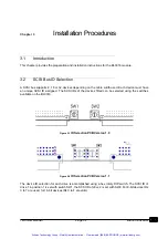
A SCSI bus supports 8, 16 or 32 devices depending on the cable width used. Each device must have
an unique SCSI ID assigned. The SCSI IDs of the devices fitted can be selected using the switches
available on the BI-0316.

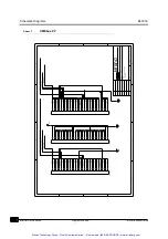
Figure 3-1 

ID Selection PCB Version 1.0

Figure 3-2 

ID Selection PCB Version 1.1

The device ID selection for each drive is accomplished using a hex rotary DIP switch. The SCSI ID of
drive 1 in position 1 is set with switch SW1, the SCSI ID of drive 2 is set with SW2. For 8-bit devices IDs
0 to 7 are used, for 16-bit devices IDs 0 to F are valid.

Artisan Technology Group - Quality Instrumentation ... Guaranteed | (888) 88-SOURCE | www.artisantg.com

Summary of Contents for BI-0316

Page 1: ...l service in house repair center WE BUY USED EQUIPMENT Sell your excess underutilized and idle used equipment We also offer credit for buy backs and trade ins www artisantg com WeBuyEquipment REMOTE INSPECTION Remotely inspect equipment before purchasing with our interactive website at www instraview com LOOKING FOR MORE INFORMATION Visit us on the web at www artisantg com for more information on ...

Page 2: ...ion 1 2 January 1999 Documentation History Date Version PCB Revision Update Level Change Description 94 03 09 1 0 1 0 First Release 94 09 09 1 1 1 0 Editorial Changes 99 01 27 1 2 1 1 PCB Changes Artisan Technology Group Quality Instrumentation Guaranteed 888 88 SOURCE www artisantg com ...

Page 3: ...r inaccuracies Brand Innovators of Digital Products bv makes no representations or warranties with respect to the contents hereof and specifically disclaims any implied warranties of merchant ability or fitness for any particular purpose Furthermore Brand Innovators of Digital Products bv reserves the right to make changes to any product herein to improve reliability function or design without obl...

Page 4: ...CSI 3 Cabling Differences 2 3 2 4 1 SCSI 2 Cabling 2 3 2 4 2 SCSI 3 Cabling 2 3 2 5 SCSI Bus Connection Options 2 3 2 5 1 SCSI 3 Option 2 3 2 5 2 SCSI 3 Mixed With SCSI 2 Option 2 4 2 6 SCSI Bus Backplane Connection Options 2 5 2 6 1 Option I Transition Module 2 5 2 6 2 Option II Flatcable Connection 2 6 2 6 3 Option III Backplane Connection 2 7 2 7 Identification 2 8 Chapter 3 Installation Proced...

Page 5: ... 2 12Vdc Pins 3 4 3 6 Installation Steps 3 5 Appendix A Block Diagram A 1 Appendix B Schematic Diagrams B 1 Appendix C Component Layout C 1 Appendix D List of Components D 1 Appendix E Connector Assignments E 1 Appendix F Drive 1 Manual F 1 Appendix G Drive 2 Manual G 1 Artisan Technology Group Quality Instrumentation Guaranteed 888 88 SOURCE www artisantg com ...

Page 6: ... Connection 2 7 Figure 3 1 ID Selection PCB Version 1 0 3 1 Figure 3 2 ID Selection PCB Version 1 1 3 1 Figure 3 3 Internal Termination PCB Version 1 0 3 2 Figure 3 4 Internal Termination PCB Version 1 1 3 2 Figure 3 5 Spindle Sync Option PCB Version 1 0 3 3 Figure 3 6 Spindle Sync Option PCB Version 1 1 3 4 Figure A 1 BI 0316 Block Diagram A 1 Figure C 1 Component Layout PCB Version 1 0 C 1 Figur...

Page 7: ...nments Single Ended E 2 Table E 3 VMEbus P2 Assignments Differential E 3 Table E 4 P3 P5 P6 SCSI 3 Connectors Single Ended E 4 Table E 5 P3 P5 P6 SCSI 3 Connectors Differential E 5 Table E 6 P7 P10 SCSI 2 Connectors Single Ended E 6 Table E 7 P7 P10 SCSI 2 Connectors Differential E 7 Table E 8 P11 P12 Power Connectors E 8 Table E 9 P14 Drive Options Jumper Block E 8 Table E 10 P15 P16 Drive Option...

Page 8: ...on page G 1 For detailed information about the SCSI standards or the software needed to operate SCSI based products see Table 1 2 Related Documents on page 1 3 Figure 1 1 View of Module 1 2 Features The BI 0316 integrates floptical and floppy disk drives hard disk drives DAT tape units mini cartridge drives and rewritable optical disk drives into compact mass storage subsystems 1 2 1 SCSI Connecti...

Page 9: ...s two shielded SCSI 3 device connec tors One on the front and another at the VMEbus P2 connector Figure 1 2 SCSI Daisy Chaining Inside the BI 0316 the SCSI signals are looped from the front to the rear connector The loop passes the connection points of the drives on the BI 0316 in such a manner that stub lengths are minimized The length of the SCSI signals on the BI 0316 is 0 90 meter 1 2 3 One Sl...

Page 10: ...es are mounted which connect to the base board using standard SCSI 2 or SCSI 3 cables The LEDs are connected to the activity and fault signals of the mounted devices Rotary switches and jumper blocks are available for SCSI ID selection and enabling of the termination of the SCSI bus signals 1 4 Manual Updates 1 5 Related Documents Table 1 1 Manual Updates Revision Changes Additions Deletions 1 0 1...

Page 11: ...General Information BI 0316 Brand Innovators Page 1 4 Technical Manual Artisan Technology Group Quality Instrumentation Guaranteed 888 88 SOURCE www artisantg com ...

Page 12: ...ng scheme is used for identification of the devices and their position on the BI 0316 Detailed information about the drives that are mounted on the BI 0316 is available in appendices Drive 1 Manual on page F 1 and Drive 2 Manual on page G 1 The numbering scheme has no relation to the SCSI IDs of the drives on the SCSI bus The numbering scheme indicates the physical order of the drives on the SCSI ...

Page 13: ...ponding maximum transfer rates are 10 20 and 40 megabytes per second Data transfers are divided into three speed classes asynchronous slow and fast A transfer period specifies the minimum time allowed between the leading edges of successive REQ pulses and of suc cessive ACK pulses while using synchronous data transfers Fast data transfers require a transfer period greater than 100 ns and less than...

Page 14: ...s A primary SCSI 3 bus P cable provides therefore a 16 bit data path A secondary SCSI 3 bus Q cable carries an additional 16 bit bus that used in conjunction with a primary SCSI 3 bus provides a 32 bit data path The BI 0316 supports the P cable option of the SCSI 3 standard 2 5 SCSI Bus Connection Options The BI 0316 can be connected to a SCSI bus initiator through the front or via the backplane c...

Page 15: ...re has to be given to the Upper Byte termination See Mixing Buses Having Different Widths on page 3 3 2 5 2 SCSI 3 Mixed With SCSI 2 Option This option uses the BI 0318 to connect to the SCSI bus signals on the VMEbus P2 Figure 2 3 SCSI 3 to SCSI 2 Daisy Chain Option Table 2 1 Termination Products for 68 pin High Density Connector Product Description Manufacturer 0 0869516 1 Amplimite 050 Series S...

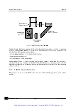
Page 16: ...tion II using a flat cable connection on the VMEbus P2 connector Option III using a special backplane layout to the VMEbus P2 connector All three options can be used for 8 bit and 16 bit solutions in Single Ended and Differential configura tions 2 6 1 Option I Transition Module This is the most common and versatile option It gives the capability to connect 8 bit and 16 bit cables to the BI 0316 It...

Page 17: ...external termination support mixing of 8 and 16 bit cables The BI 0318 and BI 0319 Transition Modules can be used in VMEbus systems that are fitted with or without a J2 backplane In either case the BI 0318 and BI 0319 provide universal solutions with their SCSI 2 and SCSI 3 type of connectors See the Technical Manual of the BI 0318 and BI 0319 for the installation details 2 6 2 Option II Flatcable...

Page 18: ...signments of the BI 0316 are given in Table E 3 VMEbus P2 Assignments Differential on page E 3 and Table E 3 VMEbus P2 Assignments Differential on page E 3 2 6 3 Option III Backplane Connection This option can be used in dedicated systems where it is known which VMEbus modules are inserted in the VMEbus backplane Figure 2 6 Option III Backplane Connection Artisan Technology Group Quality Instrumen...

Page 19: ...le E 3 VMEbus P2 Assignments Differential on page E 3 and Table E 3 VMEbus P2 Assign ments Differential on page E 3 2 7 Identification A label is used to identify the drives on the BI 0316 The text on this label includes board revision of the BI 0316 board serial number type of drive s mounted serial number of the drive s SCSI ID number of the drive s termination options installed Artisan Technolo...

Page 20: ...ed The SCSI IDs of the devices fitted can be selected using the switches available on the BI 0316 Figure 3 1 ID Selection PCB Version 1 0 Figure 3 2 ID Selection PCB Version 1 1 The device ID selection for each drive is accomplished using a hex rotary DIP switch The SCSI ID of drive 1 in position 1 is set with switch SW1 the SCSI ID of drive 2 is set with SW2 For 8 bit devices IDs 0 to 7 are used ...

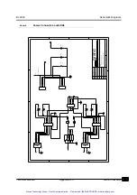
Page 21: ...ive 2 in position 2 When the BI 0316 contains drives with different widths enable the termination option for the drive with the wider bus to ensure all signals are terminated Figure 3 3 Internal Termination PCB Version 1 0 Figure 3 4 Internal Termination PCB Version 1 1 Jumper block P14 is used to enable the termination options of the drives The termination option of drive 1 in position 1 is enabl...

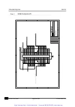
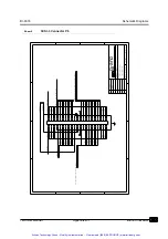
Page 22: ... 0316 which has to be connected to a 8 bit device the following products are available to provide proper termination 3 4 Spindle Sync Option When two drives of the same manufacturer and type are used then the spindle synchronization option can be activated Figure 3 5 Spindle Sync Option PCB Version 1 0 Table 3 1 Termination Products for SCSI 3 to SCSI 2 FeedThru Product Description Manufacturer 0 ...

Page 23: ...nd 12Vdc 3 5 1 5Vdc Pins The VMEbus P1 connector provides three pins for 5Vdc and another three 5Vdc pins are available on the VMEbus P2 connector These pins supply enough current for any combination of drives on the BI 0316 3 5 2 12Vdc Pins The single 12Vdc pin on the VMEbus P2 connectors allows for at least 12 Watts of power to the mounted drives This is sufficient for almost all combinations po...

Page 24: ...on the BI 0316 occupies it is necessary to jumper the daisy chain signals behind the BI 0316 to allow them to propagate down the chain The BI 0316 provides daisy chaining for the first slot it occupies see VMEbus Signals on page 1 2 b The Ground layer in the Printed Circuit Board of the BI 0316 will protect the drives from electrical interference from the boards to the left of the BI 0316 in the s...

Page 25: ...Installation Procedures BI 0316 Brand Innovators Page 3 6 Technical Manual Artisan Technology Group Quality Instrumentation Guaranteed 888 88 SOURCE www artisantg com ...

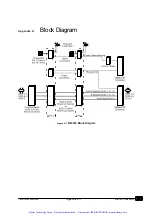
Page 26: ...Technical Manual Appendix A 1 Brand Innovators Appendix A Block Diagram Figure A 1 BI 0316 Block Diagram Artisan Technology Group Quality Instrumentation Guaranteed 888 88 SOURCE www artisantg com ...

Page 27: ...Block Diagram BI 0316 Brand Innovators Appendix A 2 Technical Manual Artisan Technology Group Quality Instrumentation Guaranteed 888 88 SOURCE www artisantg com ...

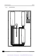
Page 28: ...hat follow the signal names are not the standard SCSI names These internal names are used to allow the BI 0316 to function in a Single Ended as well as a Differential bus Although the signal naming is not standard the electrical signals and the pin numbers of the physical connectors are conform the SCSI standards Please use the tables provided in Appendix E Connector Assignments to find the proper...

Page 29: ...N BSY ACK RST MSG SEL C D REQ I O DB 15 8 DBP1 DB 7 0 DBP ATN GND_ ATN B SY ACK RST MSG S EL C D REQ I O GND _ I O DB 15 8 DBP1 12V DIFFSENS GND_ DB0 DB 7 0 DBP P1P2 ACFAIL TERMPOWER TRACEWIDTH 100 ACFAIL ATN BSY ACK RS T MSG SEL C D R EQ I O PAGE OF OF SHEET TITLE MODULE DATE REV 4 3 2 1 D C B A A B C D 1 2 3 4 Innovators of Digital Products b v Bra nd ATN GND_ ATN B SY ACK RST MSG S EL C D REQ I...

Page 30: ...12V NC NC NC NC PWR P1 0 0164354 1 C17 C15 C18 C14 C19 C13 C20 C12 C21 C11 C22 C10 C23 C9 C24 C8 C25 C7 C26 C6 C27 C5 C28 C4 C29 C3 C30 C2 C31 C32 C1 C16 NC NC NC NC NC NC NC 1 0 MASS STORAGE MODULE BI 0316 PAGE OF OF SHEET TITLE MODULE DATE REV 4 3 2 1 D C B A A B C D 1 2 3 4 Innovators of Digital Products b v Bra nd NC NC NC NC NC NC NC NC NC NC NC NC NC NC NC NC NC NC NC NC NC NC NC NC NC NC NC...

Page 31: ...BP DB7 DB6 DB5 DB4 DB3 DB2 DB1 DB0 TERMPWR 1 0 2 MASS STORAGE MODULE BI 0316 NC NC NC NC NC NC NC NC NC NC NC NC NC NC NC NC NC NC NC NC NC NC NC NC NC PWR PAGE OF OF SHEET TITLE MODULE DATE REV 4 3 2 1 D C B A A B C D 1 2 3 4 Innovators of Digital Products b v Bra nd TERMPWR DB 15 8 DBP1 DB12 DB13 DB14 DB15 DBP1 DB8 DB9 DB10 DB11 GND_ DB0 DB 7 0 D BP GND_ DB0 DB0 DB1 DB2 DB3 DB4 DB5 DB6 DB7 DBP A...

Page 32: ...6 18 2 6 4 8 1 14 D2AC P12 0 0171826 4 1 2 3 4 P11 0 0171826 4 1 2 3 4 NC NC AC U2 74LS05 1 2 U2 74LS05 3 4 ACFAIL D2ID8 NC D2FLT D2BSY D2DC D2ID4 D2ID2 SW2 SSDRD16 F 0 C C 2 1 4 8 6 2 5 3 1 4 SW1 SSDRD16 F 0 C C 2 1 4 8 6 2 5 3 1 4 POWER CONNECTORS AND LEDS MASS STORAGE MODULE BI 0316 TERMPWR 12V C3 100UF CAP 1 2 C2 100UF CAP 1 2 100UF C1 CAP 2 1 PWR PAGE OF OF SHEET TITLE MODULE DATE REV 4 3 2 1...

Page 33: ... D R EQ I O ATN BSY ACK RST MSG SEL C D REQ I O TERMPWR P5 8 0174682 7 9 8 7 68 67 66 65 64 63 62 61 60 6 59 58 57 56 55 54 53 52 51 50 5 49 48 47 46 45 44 43 42 41 40 4 39 38 37 36 35 34 33 32 31 30 3 29 28 27 26 25 24 23 22 21 20 2 19 18 17 16 15 14 13 12 11 10 1 PAGE OF OF SHEET TITLE MODULE DATE REV 4 3 2 1 D C B A A B C D 1 2 3 4 Innovators of Digital Products b v Bra nd MASS STORAGE MODULE S...

Page 34: ... 27 28 29 3 30 31 32 33 34 35 36 37 38 39 4 40 41 42 43 44 45 46 47 48 49 5 50 51 52 53 54 55 56 57 58 59 6 60 61 62 63 64 65 66 67 68 7 8 9 TERMPWR I O REQ C D SEL MSG RST ACK BSY ATN ATN BSY ACK R ST MSG SEL C D REQ I O DIFFSENS ACK RST MSG SEL C D REQ I O BSY ATN ATN GND_ ATN BSY ACK RST MSG SEL C D REQ I O GND_ I O GND_ ATN GND_ I O DB15 DB12 DB13 DB14 DBP1 DB11 DB10 DB9 DB8 DB 15 8 DBP1 DB11 ...

Page 35: ...DB15 DBP1 DB8 DB9 DB10 DB11 DB 15 8 DBP1 DB8 DB9 DB10 DB11 DBP1 DB14 DB13 DB12 DB15 GND_ I O GND_ ATN ATN GND_ ATN B SY ACK RST MSG S EL C D REQ I O GND _ I O ATN BSY I O REQ C D SEL MSG RST ACK DIFFSENS ATN BSY ACK R ST MSG SEL C D R EQ I O ATN BSY ACK RST MSG SEL C D REQ I O TERMPWR PAGE OF OF SHEET TITLE MODULE DATE REV 4 3 2 1 D C B A A B C D 1 2 3 4 Innovators of Digital Products b v Bra nd M...

Page 36: ...RS DIFFSENS DBP DB7 DB6 DB5 DB4 DB3 DB2 DB1 DB 7 0 DBP DB0 C D SEL MSG RST ACK BSY ATN ATN BSY ACK R ST MSG SEL C D R EQ I O REQ I O NC NC NC NC P7 2 0826634 5 50 48 46 44 42 40 38 36 34 32 30 28 26 24 22 20 18 16 14 12 10 8 6 4 2 49 47 45 43 41 39 37 35 33 31 29 27 25 23 21 19 17 15 13 11 9 7 5 3 1 TERMPWR GND_ I O ATN GND_ ATN BSY ACK RST MSG SEL C D REQ I O GND_ I O I O REQ C D SEL MSG RST ATN ...

Page 37: ...8 20 22 24 26 28 30 32 34 36 38 40 42 44 46 48 50 NC NC NC NC I O REQ ATN BSY ACK RS T MSG SEL C D RE Q I O ATN BSY ACK RST MSG SEL C D DB0 DB 7 0 DBP DB1 DB2 DB3 DB4 DB5 DB6 DB7 DBP DIFFSENS SCSI 2 CONNECTORS MASS STORAGE MODULE BI 0316 PAGE OF OF SHEET TITLE MODULE DATE REV 4 3 2 1 D C B A A B C D 1 2 3 4 Innovators of Digital Products b v Bra nd 1 0 GND_ DB0 DB0 DB1 DB2 DB3 DB4 DB5 DB6 DB7 DBP ...

Page 38: ...RST MSG SEL C D REQ I O GND_ I O GND_ I O TERMPWR NC NC NC NC I O REQ ATN BSY ACK R ST MSG SEL C D R EQ I O ATN BSY ACK RST MSG SEL C D DB0 DB 7 0 DBP DB1 DB2 DB3 DB4 DB5 DB6 DB7 DBP DIFFSENS SCSI 2 CONNECTORS MASS STORAGE MODULE BI 0316 PAGE OF OF SHEET TITLE MODULE DATE REV 4 3 2 1 D C B A A B C D 1 2 3 4 Innovators of Digital Products b v Bra nd 1 0 GND_ DB0 DB0 DB1 DB2 DB3 DB4 DB5 DB6 DB7 DBP ...

Page 39: ... RST MSG SEL C D REQ I O GND_ I O GND_ I O TERMPWR NC NC NC NC I O REQ ATN BSY ACK RS T MSG SEL C D RE Q I O ATN BSY ACK RST MSG SEL C D DB0 DB 7 0 DBP DB1 DB2 DB3 DB4 DB5 DB6 DB7 DBP DIFFSENS SCSI 2 CONNECTORS MASS STORAGE MODULE BI 0316 PAGE OF OF SHEET TITLE MODULE DATE REV 4 3 2 1 D C B A A B C D 1 2 3 4 Innovators of Digital Products b v Bra nd 1 0 GND_ DB0 DB0 DB1 DB2 DB3 DB4 DB5 DB6 DB7 DBP...

Page 40: ...nical Manual Appendix C 1 Brand Innovators Appendix C Component Layout Figure C 1 Component Layout PCB Version 1 0 Artisan Technology Group Quality Instrumentation Guaranteed 888 88 SOURCE www artisantg com ...

Page 41: ...ponent Layout BI 0316 Brand Innovators Appendix C 2 Technical Manual Figure C 2 Component Layout PCB Version 1 1 Artisan Technology Group Quality Instrumentation Guaranteed 888 88 SOURCE www artisantg com ...

Page 42: ... III Without Boardlocks With 2 84 Solder Tails P5 P6 8 0174682 7 AMPLIMITE Subminiature Connector Receptacle header Right Angle mount No of positions 68 With self retaining sol der Posts P7 P10 2 0826634 5 MODU II Pin Header 2x25 Positions Right Angle mount P11 P12 0 0171826 4 Connector EI series 4 Positions Right Angle mount P14 0 0826632 5 MODU II Pin Header 2x5 Positions P15 P16 0 0825457 6 MOD...

Page 43: ...List of Components BI 0316 Brand Innovators Appendix D 2 Technical Manual Artisan Technology Group Quality Instrumentation Guaranteed 888 88 SOURCE www artisantg com ...

Page 44: ...D13 7 D06 BG1OUT D14 8 D07 BG2IN D15 9 GND BG2OUT GND 10 SYSCLK BG3IN SYSFAIL 11 GND BG3OUT BERR 12 DS1 BR0 SYSRESET 13 DS0 BR1 LWORD 14 WRITE BR2 AM5 15 GND BR3 A23 16 DTACK AM0 A22 17 GND AM1 A21 18 AS AM2 A20 19 GND AM3 A19 20 IACK GND A18 21 IACKIN SBUS_DATA A17 22 IACKOUT SBUS_STRB A16 23 AM4 GND A15 24 A07 IRQ7 A14 25 A06 IRQ6 A13 26 A05 IRQ5 A12 27 A04 IRQ4 A11 28 A03 IRQ3 A10 29 A02 IRQ2 A...

Page 45: ...DB P1 A25 GND 6 DB 0 A26 GND 7 DB 1 A27 GND 8 DB 2 A28 GND 9 DB 3 A29 GND 10 DB 4 A30 GND 11 DB 5 A31 GND 12 DB 6 GND GND 13 DB 7 5V GND 14 DB P D16 GND 15 GND D17 GND 16 GND D18 GND 17 TERMPWR D19 TERMPWR 18 GND D20 GND 19 ATN D21 GND 20 GND D22 GND 21 BSY D23 GND 22 ACK GND GND 23 RST D24 GND 24 MSG D25 GND 25 SEL D26 GND 26 C D D27 GND 27 REQ D28 GND 28 I O D29 12V 29 DB 8 D30 GND 30 DB 9 D31 G...

Page 46: ...25 DB P1 6 GND A26 GND 7 DB 0 A27 DB 0 8 DB 1 A28 DB 1 9 DB 2 A29 DB 2 10 DB 3 A30 DB 3 11 DB 4 A31 DB 4 12 DB 5 GND DB 5 13 DB 6 5V DB 6 14 DB 7 D16 DB 7 15 DB P D17 DB P 16 GND D18 DIFFSENS 17 TERMPWR D19 TERMPWR 18 ATN D20 ATN 19 GND D21 GND 20 BSY D22 BSY 21 ACK D23 ACK 22 RST GND RST 23 MSG D24 MSG 24 SEL D25 SEL 25 C D D26 C D 26 REQ D27 REQ 27 I O D28 I O 28 GND D29 12V 29 DB 8 D30 DB 8 30 ...

Page 47: ...B 2 GND 9 43 DB 3 GND 10 44 DB 4 GND 11 45 DB 5 GND 12 46 DB 6 GND 13 47 DB 7 GND 14 48 DB P GND 15 49 GND GND 16 50 GND TERMPWR 17 51 TERMPWR TERMPWR 18 52 TERMPWR RESERVED 19 53 RESERVED GND 20 54 GND GND 21 55 ATN GND 22 56 GND GND 23 57 BSY GND 24 58 ACK GND 25 59 RST GND 26 60 MSG GND 27 61 SEL GND 28 62 C D GND 29 63 REQ GND 30 64 I O GND 31 65 DB 8 GND 32 66 DB 9 GND 33 67 DB 10 GND 34 68 D...

Page 48: ...DB 2 9 43 DB 2 DB 3 10 44 DB 3 DB 4 11 45 DB 4 DB 5 12 46 DB 5 DB 6 13 47 DB 6 DB 7 14 48 DB 7 DB P 15 49 DB P DIFFSENS 16 50 GND TERMPWR 17 51 TERMPWR TERMPWR 18 52 TERMPWR RESERVED 19 53 RESERVED ATN 20 54 ATN GND 21 55 GND BSY 22 56 BSY ACK 23 57 ACK RST 24 58 RST MSG 25 59 MSG SEL 26 60 SEL C D 27 61 C D REQ 28 62 REQ I O 29 63 I O GND 30 64 GND DB 8 31 65 DB 8 DB 9 32 66 DB 9 DB 10 33 67 DB 1...

Page 49: ...7 8 DB 3 GND 9 10 DB 4 GND 11 12 DB 5 GND 13 14 DB 6 GND 15 16 DB 7 GND 17 18 DB P GND 19 20 GND GND 21 22 GND RESERVED 23 24 RESERVED OPEN 25 26 TERMPWR RESERVED 27 28 RESERVED GND 29 30 GND GND 31 32 ATN GND 33 34 GND GND 35 36 BSY GND 37 38 ACK GND 39 40 RST GND 41 42 MSG GND 43 44 SEL GND 45 46 C D GND 47 48 REQ GND 49 50 I O Artisan Technology Group Quality Instrumentation Guaranteed 888 88 S...

Page 50: ... 2 DB 3 9 10 DB 3 DB 4 11 12 DB 4 DB 5 13 14 DB 5 DB 6 15 16 DB 6 DB 7 17 18 DB 7 DB P 19 20 DB P DIFFSENS 21 22 GND RESERVED 23 24 RESERVED TERMPWR 25 26 TERMPWR RESERVED 27 28 RESERVED ATN 29 30 ATN GND 31 32 GND BSY 33 34 BSY ACK 35 36 ACK RST 37 38 RST MSG 39 40 MSG SEL 41 42 SEL C D 43 44 C D REQ 45 46 REQ I O 47 48 I O GND 49 50 GND Artisan Technology Group Quality Instrumentation Guaranteed...

Page 51: ...Mnemonic Pin Number Pin Number Signal Mnemonic D1TERM 1 2 GND GND 3 4 GND D1SYNC 5 6 D2SYNC D1SYNC 7 8 D2SYNC D2TERM 9 10 GND Table E 10 P15 P16 Drive Options Connector Signal Mnemonic Pin Number Pin Number Signal Mnemonic SEL0 1 2 XTFALT SEL1 3 4 VUNIQ SEL2 5 6 SPSYNC SEL3 7 8 XTACTV ENTERM 9 10 GROUND 5V 11 12 FAULT Artisan Technology Group Quality Instrumentation Guaranteed 888 88 SOURCE www ar...

Page 52: ... Appendix F Drive 1 Manual Table F 1 Jumper Setting Drive 1 Jumper Function Factory Default Setting Brand Innovators Setting User Setting No Drive Installed Artisan Technology Group Quality Instrumentation Guaranteed 888 88 SOURCE www artisantg com ...

Page 53: ...Drive 1 Manual BI 0316 Brand Innovators Appendix F 2 Technical Manual Artisan Technology Group Quality Instrumentation Guaranteed 888 88 SOURCE www artisantg com ...

Page 54: ...1 Jumper Setting Drive 2 JAZ Jumper Function Factory Default Setting Brand Innovators Setting User Setting SCSI ID fixed 4 fixed 4 SW2 inoperable Termination external external P14 inoperable Artisan Technology Group Quality Instrumentation Guaranteed 888 88 SOURCE www artisantg com ...

Page 55: ...Drive 2 Manual BI 0316 Brand Innovators Appendix G 2 Technical Manual Artisan Technology Group Quality Instrumentation Guaranteed 888 88 SOURCE www artisantg com ...

Page 56: ...l service in house repair center WE BUY USED EQUIPMENT Sell your excess underutilized and idle used equipment We also offer credit for buy backs and trade ins www artisantg com WeBuyEquipment REMOTE INSPECTION Remotely inspect equipment before purchasing with our interactive website at www instraview com LOOKING FOR MORE INFORMATION Visit us on the web at www artisantg com for more information on ...

Reviews: