25
•
ASSEMBLING THE HOOD
Warning
The hood must be installed in compliance
with all applicable regulations concerning the
ventilation of premises. In France these
regulations are described in DTU 61.1 from the
CSTB. In particular, the evacuated air should
never be conveyed to a duct used to evacuate
smoke from appliances that use gas or other
combustible fuels. Unused ducts may only be
used after approval from a competent specialist.
The distance between the supporting surface for
the cooking vessels on the hob and the lower part
of the hood must be at least 650 mm. If the
instructions for installation for the hob specify a
greater distance, this has to be taken into account.
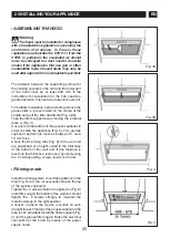
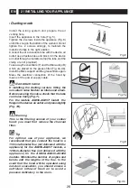
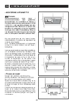
To facilitate installation, before starting remove the
grease filter /s: press inward on the clamp at the
handle and pull the filter downward (Fig. a/3b).
Take the filters support away moving the 2 lateral
locks A (Fig. 4).
Cut a hole in the bottom of the pensile cupboard in
order to settle the appliance (Fig. 5). The pensile
cupboard bottom hob must be between 15 and I
18 mm thick.
Check that the fixing tabs (Fig. 6) to the wall unit
are positioned at a height suited to the thickness
of the bottom of the wall unit. If this distance is
less than the thickness, increase it by unscrewing
the 2 corresponding screws inside the hood.
•
Filtering mode
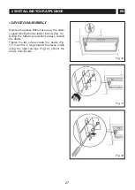
Install the wiring system. Insert the appliance in the
hole (Fig. 5). Cut the air evacuation hole on the top
of the pensile cupboard.
Tighten the 2 screws inside the appliance (Fig. 8)
until it fits snug on the bottom of the wall unit. Do not
tighten the 2 screws strongly to maintain the
metallic clamps in the right position.
Connect a tube to the device air outlet, on such
a height to reach the top of the pensile cupboard (the
tube is not provided).Install the filters support (Fig.
4) and the grease filters again. Make the electrical
connection of the hood by means of the power
supply cable.
2 / INSTALLING YOUR APPLIANCE
EN
Fig. 3a
Fig. 3b
Fig. 4
Fig. 5


