5
-
0
bRANSON 9550C
CONTROL AND OPERATION OF HYDRAULIC SYSTEM
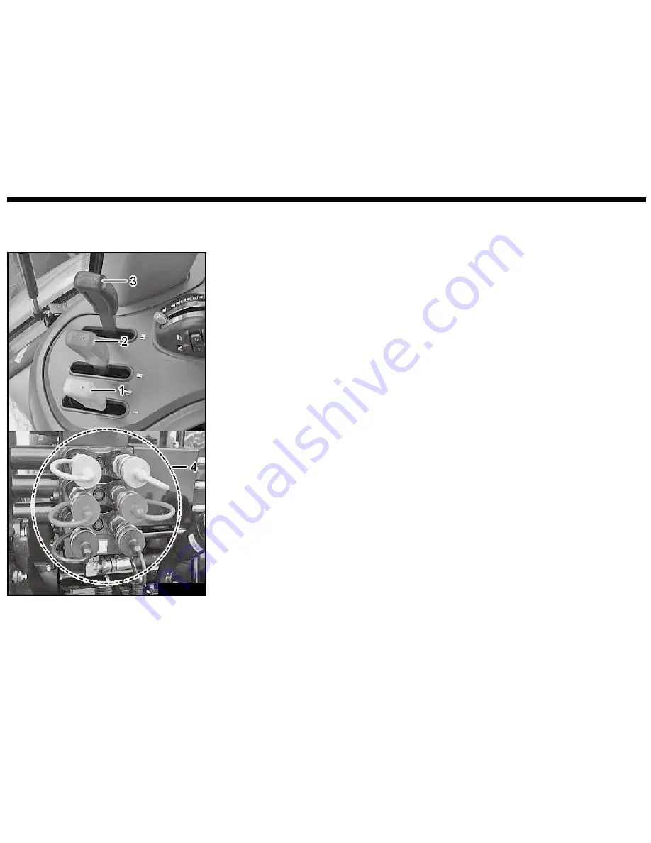
SCV CONTROL LEVER AND COUPLER
BR95O518A
(1) SVC Control Lever 1
(2) SVC Control Lever 2
(3) SVC Control Lever 3
(4) Coupler
CYLINDER HOSE CONNECTION
Levers (1,2,3) are controlled the oil
flow and flow rate.
Left coupler is for extension, right
coupler is for retraction.
1. Differentiate the extension hose
from the retraction hose. Exten-
sion hose should be connected to
the right coupler.
Retraction hose should be con-
nected to the left coupler.
2. Remove the dust cap from the end
of the hose.
3. Open the coupler cap.
4. Check if the end of the hose and
the coupler are clean. Insert the
hose tip into the coupler correctly.
Pull the hose once to check it the
hose is exactly inserted into the
coupler.
5. Match the color both of the lever
handle and the valve cap.
6. When connect the outside hy-
draulic hose, be sure not to intro-
duce foreign material. Necessar-
ily install the connector which is
cleaned.
Summary of Contents for 9550C
Page 2: ...BRANSON 9550C 00 indd 2 2015 12 22 8 53...
Page 47: ...2 2 ABOUT WARRANTY WARRANTY 2 2 TROUBLE SHOOTING 2 2 BRANSON 9550C 02 indd 1 2015 12 15 3 31...
Page 49: ...3 3 OVERVIEW OF THE TRACTOR EXTERIOR VIEW 3 2 BRANSON 9550C 03 indd 1 2015 12 22 8 54...
Page 52: ...MEMO Branson Machinery LLC BRANSON 9550C 03 indd 4 2015 12 22 8 54...
Page 154: ...MEMO Branson Machinery LLC BRANSON 9550C 07 indd 24 2015 12 16 2 32...
Page 166: ...MEMO Branson Machinery LLC BRANSON 9550C 09 indd 6 2015 12 16 8 47...
Page 167: ...10 INDEX 10 2 10 INDEX BRANSON 9550C 10 indd 1 2015 12 16 2 12...


