Chapter 2: Introduction to the SLPt Cell Disruptor
Controls and Commands
2-2
100-214-252 Rev. A
The digital controls on the SLPt Cell disruptor allow for accuracy and repeatability of control settings.
Application parameters are entered into the power supply through the keypad on the front panel of the unit.
External signals are initiated via J2 (9 pin) connector on the back of the power supply. To simply generate
a start signal, a J911 Start cable, 8’, (EDP101-240-020) can be used. To control or monitor other signals
(Reset, Seek, Alarm, Ready) a J913 Start cable, 25’, (EDP101-240-072) must be used. Reset and Start func-
tions can also be performed from the front panel. Further information about these signals can be found in
Section 4.6.2. All other functions can only be performed from the front panel.
The SLPt Cell Disruptor’s power supply converts AC line voltage to 40kHz electrical energy. This high-
frequency electrical energy is fed to a converter where it is converted to mechanical vibrations. The heart of
the converter is a lead zirconate titanate electrostrictive element which, when subjected to an alternating
voltage, expands and contracts. The converter vibrates in a longitudinal direction and transmits this motion
to the tool immersed in the solution, which causes cavitation. The implosion of microscopic cavities in the
solution results, causing the molecules in the medium to become intensely agitated. The ultrasonic vibra-
tions transmitted through the tool can also be applied directly to a solid workpiece, such as tissue, through
the tool that are attached to the converter.
The SLPt Cell Disruptor is a constant amplitude device. As the load or pressure on the tool face increases,
the power supply develops more power to maintain the amplitude for any given output control setting. When
the tool is operated in air, it is subjected to minimum pressure, and minimum power is required to maintain
amplitude.
The load increases when the tool is immersed in a liquid; the more viscous the liquid, the higher the load
and the more power developed. If a cell that can be pressurized is used, even more power is developed. For
any given application, more power results when a tool of higher amplitude or larger radiating surface is
used, or when any tool is driven at higher amplitude by increasing the amplitude.
By setting various operation parameters, you can precisely control the way in which ultrasonics are applied
to the sample. You can:
•
Specify the time duration of the experiment
•
Adjust the amplitude setting between 10% and 60% of maximum amplitude (microtip 60% max-
imum)
•
Prevent excessive temperature increase in the sample by setting ultrasonics to operate in Pulse
mode or in Pulse/Pause mode
•
Bring a sample to a desired temperature and hold it there, varying by only a few degrees, for a
desired duration using the Pulse/Pause mode
2.2 Controls and Commands
This section describes the controls and commands that you use to operate the SLPt Cell disruptor. A detailed
description of how and when to use each front panel control, the valid formats for the data that you enter,
and the response you receive from the system when you use each of these controls is provided in
Chapter
6, Operations
.
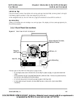
The SLPt Cell disruptor is equipped with a keypad and LED display on the front panel of the unit. With the
keypad, you can set functional modes of operation and input digital parameters. Availability of the various
functions depends on the mode or state of the system. If you attempt to use a function that is not available,
you will be alerted by a beep.
DOC EXPIRES 12PM 9/16/2007. Article or Material must comply with the requirements
stipulated by RoHS in its current version of 1/27/03


