SLPt Cell Disruptor
Chapter 2: Introduction to the SLPt Cell Disruptor
User Manual
Controls and Commands
100-214-252 Rev. A
2-5
Left Arrow Key
The Left Arrow key selects from right to left, causing each digit in turn to blink, and wraps back to the right.
The blinking digit is available to increment using the Up Arrow key.
In the configuration menu , the Left Arrow key toggles the function between Off (0) and On (1).
Up Arrow Key
This key will increment a selected digit, one count per press. The display will increment appropriately for
the selected parameter.
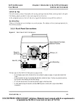
2.2.2 Back Panel Connections
Figure 2.3
Back Panel of SLPt Cell Disruptor
The back panel of the SLPt Cell Disruptor is equipped with:
•
An IEC-type power cord connection for connecting the power supply to a grounded electrical
outlet.
•
A fuse holder for access to a replaceable 5x20mm protective fuse. The fuse is a glass
slow-blow
type (refer to the data tag for the fuse rating).
•
A 3 pin RF
connector to connect the power supply to the Converter.
•
A User external input connector (female DB9f requires a cable with a 9-pin male DB9m
connector).
RF
Serial Num.
INPUT:
Year
& Month of Manufacture
MAX POWER:
MODEL
EDP NO.
J 2
User I/O, J2
RF Out, J3
Ground Detect Terminal,
Optional Feature
Power In,
and Fuse
Unit Data Tag
DOC EXPIRES 12PM 9/16/2007. Article or Material must comply with the requirements
stipulated by RoHS in its current version of 1/27/03


