Chapter 4: Installation and Setup
Ultrasonic Test
4-10
100-214-252 Rev. A
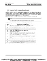
4.8 Ultrasonic Test
The Test button on the front panel of the SLPt Cell Disruptor is used to verify that the unit is functioning
(providing ultrasonic energy to the Converter and Horn). Later, you can run another test on the system for
your particular experiment (described in
5.3 System Performance Benchmark
).
Before testing the SLPt, always make sure that the horn is not touching anything. The System also performs
several self-tests when it is first turned on.
Use the following charts to determine the correct system settings for
the tools you are using.
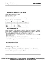
Table 4.3
Approximate Microtip Amplitudes in Microns
Step
Do this...
To obtain this result
1
Set up the SLPt Cell Disruptor follow-
ing the instructions in this manual.
Connect the microtip to the converter.
Prepare the Sonifier to operate, if it was not previ-
ously assembled.
2
Connect the RF cable to the power
supply. Turn the Unit On, and observe
the self-test displays.
Verify that the system passes all its self-tests,
observing that there are no error messages on the
front panel display.
The SLPt Cell Disruptor advances to the “Ready”
mode and shows the normal Ready display .
3
Adjust the Amplitude control to
approximately 50% (observe the
value on the front panel display).
Ensures that ultrasonic energy will be at some mid-
range value, and will not cause damage. Refer to
Table 4.3 for amplitude information.
4
Verify that the Horn is not touching
anything.
Press and hold the Test button
on
the front panel. The test will run until
the test key is released. Observe the
front panel display.
Verifies the ultrasonic output of the system. You may
hear a soft, high-pitched sound.
5
If the system showed readings on
the display during the Test,
you may either proceed with your
experiments, or
Turn the unit off.
Verification that the SLPt Cell Disruptor is operating
and is ready to be set up for your experiment.
Microtip EDP No.
Description
Amplitude Control Settings
10%
40%
70%
109-122-1064
0.250” Diameter Tapered
5
15
30
109-122-1182
0.190” Diameter Tapered
12
38
74
109-122-1065
0.125” Diameter Tapered
12
34
68
109-122-1066
0.091” Diameter Tapered
14
32
64
* All measurements in microns unless otherwise specified
DOC EXPIRES 12PM 9/16/2007. Article or Material must comply with the requirements
stipulated by RoHS in its current version of 1/27/03


