background image

Chapter 5: Technical Specifications
Physical Description

5-2

100-214-252 Rev. A

5.2 Physical Description

The following table outlines the physical characteristics of the Digital Sonifier.

Converter Weight with cable

1.1 lbs. (0.5kg)

Converter Length

 5”, (127mm)

Converter Diameter

 1.5” (38mm)

Converter to Microtip Stud

M8 x 1.25

Horn Tip Diameters

0.091, 0.125 and 0.250 (2.3 – 6.4 mm), depending on process needs.

Overall Dimensions

12 1/2" L x 7 1/2" W x 9 1/4"H (318x191x235 mm) excluding RF out 
‘connector (5/8",16mm), 

Power Supply Weight

150 Watt unit = 14 lbs, 10 oz. (


6.5kg),

DOC EXPIRES 12PM 9/16/2007. Article or Material must comply with the requirements
                             stipulated by RoHS in its current version of 1/27/03

Summary of Contents for Sonifier SLPt

Page 1: ...DP 100 214 252 Rev A BRANSON Ultrasonics Corporation 41 Eagle Road Danbury Connecticut 06813 1961 U S A 203 796 0400 DOC EXPIRES 12PM 9 16 2007 Article or Material must comply with the requirements st...

Page 2: ...nt and refer to the printing date which appears in the lower right corner of this page Patents and Copyright Copyright 2003 by Branson Ultrasonics Corporation Danbury Connecticut U S A All rights rese...

Page 3: ...nual This manual is arranged into seven structured chapters which will help you find the infor mation you may need to know to safely handle install set up program operate and or maintain this product...

Page 4: ...100 214 252 Rev A For Your Notes DOC EXPIRES 12PM 9 16 2007 Article or Material must comply with the requirements stipulated by RoHS in its current version of 1 27 03...

Page 5: ...and Commands 2 2 2 2 1 SLPt Cell Disruptor Keypad Display Description 2 4 2 2 2 Back Panel Connections 2 5 2 3 System Features 2 6 Chapter 3 Delivery and Handling 3 1 Delivery and Handling 3 1 Chapter...

Page 6: ...nu Navigation 6 4 6 3 2 Configuration Menu 6 4 6 3 3 Control Menu 6 5 6 4 Operational Sequence 6 7 6 4 1 SLPt in Continuous Mode 6 7 6 4 2 SLPt in Time Mode Either Low min sec or High hr min 6 8 6 4 3...

Page 7: ...type wall receptacle DO NOT under any circumstances remove the power cord ground prong DO NOT operate the equipment with the cover removed High voltage is present within the equipment when connected...

Page 8: ...ome materials and depolymerize others 1 2 2 Safety Measures and Guards This manual contains operation instructions for the SLPt Cell Disruptor It contains information essential to the proper use and c...

Page 9: ...g the SLPt Cell Disruptor to prevent possible splash injury originating in the solution WARNING Never touch the horn or tip when ultrasonics are active Touching the horn or tip while the unit is on ca...

Page 10: ...EN61000 3 2 EN61000 3 3 EN61000 4 3 EN61000 4 5 EN61000 4 6 EN61000 4 11 IEC61000 4 2 A1 IEC61000 4 4 Following the provision of Low Voltage Directive 73 23 EEC amended by directive 93 68 EEC EMC Dir...

Page 11: ...transportation charges prepaid A limited warranty as specified may apply to certain components of the equipment WARRANTY EXCEPTIONS This warranty shall not apply to equipment subjected to misuse impro...

Page 12: ...el on the units Information about the Horn part number gain etc or other tooling may be etched into the tooling Software or firmware based systems may provide a software version number which may be re...

Page 13: ..._______________________ ________________________________________________________________________ 5 What is your application e g continuous pulse etc ___________________________________________________...

Page 14: ...umber on the outside of cartons as well as on your pack ing slip along with the reason for return Return general repairs by any convenient method Send priority repairs by air freight You must prepay t...

Page 15: ...Description 2 4 2 2 2 Back Panel Connections 2 5 2 3 System Features 2 6 2 1 Overview of SLPt Cell Disruptor The SLPt Cell Disruptor is often used by laboratory personnel in the medical and chemical...

Page 16: ...he amplitude for any given output control setting When the tool is operated in air it is subjected to minimum pressure and minimum power is required to maintain amplitude The load increases when the t...

Page 17: ...the unit You always have the ability to halt operation whether control is direct or remote Section 2 2 2 Back Panel Connections on page 2 5 describes the back panel of the unit Enter Reset Test Start...

Page 18: ...rameter being modified and then return the system to Ready It will also reset the power supply and clear any alarms Test Key The Test key is only active when the system is ready Ultrasonics are enable...

Page 19: ...ck Panel of SLPt Cell Disruptor The back panel of the SLPt Cell Disruptor is equipped with An IEC type power cord connection for connecting the power supply to a grounded electrical outlet A fuse hold...

Page 20: ...brane front panel with numeric keypad for parameter entry and function selection Digital parameter setting with valid parameter range checking Pulse or Continuous operation Digital Timer Automatic end...

Page 21: ...ect the carton for signs of damage 2 Open the carton and locate the packing list 3 Carefully unpack the components and check them against the packing list 4 Save all packing materials in case the equi...

Page 22: ...livery and Handling Delivery and Handling 3 2 100 214 252 Rev A For Your Notes DOC EXPIRES 12PM 9 16 2007 Article or Material must comply with the requirements stipulated by RoHS in its current versio...

Page 23: ...4 2 Connecting Microtips and Converters 4 7 4 5 Input Power Requirements 4 8 4 6 Electrical Connections to Equipment 4 8 4 6 1 Power Cord 4 8 4 6 2 User I O Connection 4 9 4 7 Guards and Safety Equipm...

Page 24: ...3 System Component Description 4 3 1 Standard Components The standard system components are SLPt Sonifier power supply AC Power cord Ultrasonic converter Microtip 1 8 tapered Wrench set Manual Power...

Page 25: ...meet specific application needs Figure 4 1 Tapered Microtip requires another spanner wrench P N 201 118 024 in addition to the one supplied in the tool kit CAUTION DO NOT allow the horn or microtip t...

Page 26: ...gs for small volumes To prevent foaming or aerosoling while processing small quantities with the tapered microtips the use of a conical shaped tube such as a reaction vial or a cut down centrifuge tub...

Page 27: ...und proof Enclosure can be used to reduce this to an acceptable level It is especially useful when the Sonifier is used for extended periods of time The Soundproof Enclosure is also useful at minimizi...

Page 28: ...in a vise If necessary secure the largest portion of the microtip in a soft jawed vise See Section 4 4 2 Connecting Microtips and Converters on page 4 7 Step Action 1 Connect the microtip to the conve...

Page 29: ...be installed clean and dry or the power supply may not tune and operate correctly Step Action 1 Clean the contacting surfaces of the converter and microtip and remove any foreign matter from the thre...

Page 30: ...the connections to the SLPt Cell Disruptor are made to the rear of the unit using industry standard connectors Refer to Figure 2 3 Back Panel of SLPt Cell Disruptor on page 2 5 for connector locations...

Page 31: ...otection for safe operation Appropriate eye protection should be worn when operating the SLPt to prevent possible splash injury orig inating in the solution WARNING The Ultrasonic Horn can cause injur...

Page 32: ...sages on the front panel display The SLPt Cell Disruptor advances to the Ready mode and shows the normal Ready display 3 Adjust the Amplitude control to approximately 50 observe the value on the front...

Page 33: ...d perform an executable Reset Test Enter Start Stop on front panel membrane On Off rocker switch to turnn on power to the unit Duty Cycle Intermittent pulse duration adjustable 0 1 seconds 99hrs 59 mi...

Page 34: ...th 5 127mm Converter Diameter 1 5 38mm Converter to Microtip Stud M8 x 1 25 Horn Tip Diameters 0 091 0 125 and 0 250 2 3 6 4 mm depending on process needs Overall Dimensions 12 1 2 L x 7 1 2 W x 9 1 4...

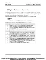
Page 35: ...on the following page 2 Identify your experiment type on the form for your own reference Set up the Digital Sonifier be ready to run and prepare your experiment 3 Turn the SLPt system On 4 Select Mode...

Page 36: ..._________________________________ Converter Serial Number __________________________________________________ Tool Type __________________________________________________ Parameters Modes _____________...

Page 37: ...inuous Mode 6 8 6 4 2 SLPt in Time Mode Either Low min sec or High hr min 6 9 6 4 3 SLPt in Time Mode with Pulse Either Low min sec or High hr min 6 9 6 5 Alarms 6 10 6 1 Front Panel Controls 6 1 1 Po...

Page 38: ...y Membrane CAUTION Do not use a sharp or pointed object to press the front panel controls The soft touch mem brane front panel can be permanently damaged Enter Reset Test Start Stop Mode 88 88 Continu...

Page 39: ...his time the power supply is also reset and cleared of any alarms Test Sets up resonant frequency This key is only active when the system is ready Pressing Test will turn on sonics and hold them on un...

Page 40: ...u Stop the cycle Timed Mode Ultrasonics are applied to the sample for a period of time that you specify by setting the Time On parameter Pulse Mode Set pulse length of Time for Experiment parameter In...

Page 41: ...splay will go to the ready state and displays rdY ready There are two groups of addressable functions Mode and Set The current Mode LED will be on Pressing the Mode button will sequence to the next mo...

Page 42: ...e 3 beeps The system will not accept out of range parameters Table 6 2 Mode Set parameter Continuous Amplitude Time min sec On Off Amplitude Time hr min On Off Amplitude Time min sec with Pulse On Off...

Page 43: ...pply to selected item as desired 4 Press ENTER to accept choices and exit the Configuration Menu Set Power Supply Wattage 1 Press TEST 5 while powering up All Set LED s 3 will blink 2 Set wattage to m...

Page 44: ...ected The On 3A Off 3C Amplitude 3D and Experiment Time 3E LED s will light 3 Set the Time On Off time Amplitude and Exp time using the arrow keys 4 Press ENTER 5 Send Start pulse by shorting pins 2 a...

Page 45: ...Action Er OL Power Supply Overload Depending on configuration Reset the power supply Refer to 6 3 2 Configuration MenuTurn off unit and power up again If the message repeats check Peak Power to verify...

Page 46: ...Chapter 6 Operation Alarms 6 10 100 214 252 Rev A DOC EXPIRES 12PM 9 16 2007 Article or Material must comply with the requirements stipulated by RoHS in its current version of 1 27 03...

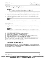
Page 47: ...1 System Trouble Analysis Chart on page4 to locate the symptom that most clearly describes your problem Tip Erosion Microtips can erode Tip erosion is a side effect of the cavitation process that occu...

Page 48: ...between metal parts that appears on the mating metal surfaces Corrosion can reduce or alter system performance Examine the mating sur face tool to converter and wipe the surfaces clean with a clean cl...

Page 49: ...cloth NOTE ii Do not apply downward pressure The weight of the part alone provides sufficient pressure 5 Rotate the part 120 degrees 1 3 6 Stroke the part an equal number of times at each rotation 2 o...

Page 50: ...r Fan does not operate when system is turned on Display screen appears Fan motor has failed Return for repair Fuse fails when system is turned on Fuse is under rated Mains Voltage is incorrect Fan mot...

Page 51: ...ching a metal part of the system or lab equip ment contacting the sys tem System is not properly grounded Correct electrical ground to system Cordset has failed or had Ground lead removed replace cord...

Page 52: ...ce Interconnect Diagram 7 6 100 214 252 Rev A F4 F3 BLU BRN 7 4 Interconnect Diagram DOC EXPIRES 12PM 9 16 2007 Article or Material must comply with the requirements stipulated by RoHS in its current...

Page 53: ...omponents standard 4 2 Connecting Microtips and Converters 4 7 Continuous Mode 6 4 Controls and Commands 2 2 Controls Front Panel 6 1 Converters Connecting Microtip to 4 7 D Description Physical 5 2 D...

Page 54: ...Intended Use of the System 1 2 Interconnect Diagram 7 6 Introduction to the SLPt 2 1 K Keypad Display Description 2 4 M Maintenance 7 1 Membrane front panel display 6 2 Membrane Keypad 6 2 Microtip C...

Page 55: ...tory Compliance 1 4 S Safety 1 1 Safety Considerations 1 1 Safety Equipment 4 9 Safety Measures 1 2 Setting Up the Workplace 1 3 setup 4 1 Setup Form 5 4 Setup Procedure 4 6 SLPt SLPe Setup Form 5 3 S...

Page 56: ...1 Timed Mode 6 4 Tip Erosion 7 1 Troubleshooting 7 1 U Ultrasonic Test 4 10 User I O 4 9 W Warranty statement 1 5 Workplace setting up 1 3 DOC EXPIRES 12PM 9 16 2007 Article or Material must comply w...

Reviews: