Page 7
Switch LED Diagnostics
Lift Out Switch:
The Lift Out Switch stops in-
ward travel of the carriage/platform during Stow
function (activated by the housing-mounted Lift
Out Cam). Move cam in to increase inward
travel. Move cam out to decrease inward travel.
Diagnostic LED “LIFT OUT” will be illuminated
when the switch is not contacting the cam.
Full Out Switch:
The Full Out Switch stops
outward travel of the carriage/platform during
Deploy (Up/Down) functions (activated by the
housing-mounted Full Out Cam). Move cam in
to decrease outward travel. Move cam out to
increase outward travel. Carriage rollers must
be inside housing a minimum 1.3 cm (1/2"). The
platform will not raise or lower until this switch
is activated. Diagnostic LED “FULL OUT” will
be illuminated when the switch is contacting the
cam.
Carriage Ride Height Adjustment
7KHFDUULDJHKRUL]RQWDODUPVPRYHUROOLQDQG
out of the housing tracks on roller bearings.
)ROORZLQJLQVWDOODWLRQRUH[WHQVLYHOLIWRSHUDWLRQ
FOHDUDQFHEHWZHHQKRUL]RQWDODUPVDQGWUDFNV
may diminish. The eccentric shaft mounting
plate allows height adjustment.
Remove eccentric plate mounting screw. Us-
LQJVFUHZGULYHURUVPDOOURGURWDWHWKHVKDIW
clockwise to increase carriage height. Rotate
the shaft counterclockwise to decrease carriage
height. Reinstall mounting screw in nearest
retainer hole. Adjust left and right side eccentric
shafts (screw positions may vary from side to
VLGH$GMXVWKHLJKWVXFKWKDWKRUL]RQWDODUPVGR
not contact top or bottom of tracks (align center).
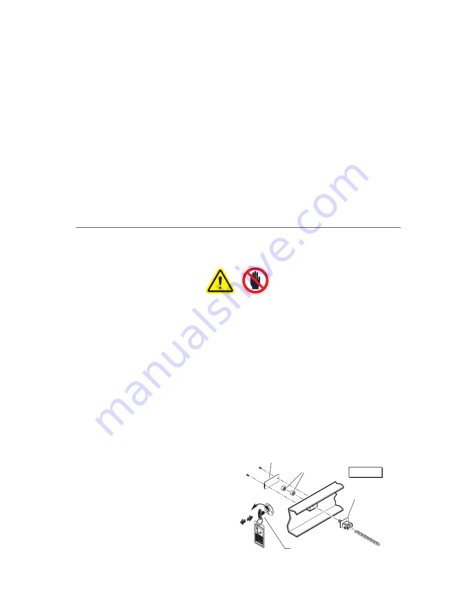
Drive Chain Adjustment
In event the drive chain sags 1.3 cm (1/2") or
PRUHDGMXVWWHQVLRQDVGHWDLOHG7LJKWHQWR
eliminate visible sag but do not overtighten.
1. Unlock and pull the manual release cable
and lock in released position.
0DQXDOO\H[WHQGSODWIRUPFDUULDJHIXOORXW
3. Remove adjustment bolt (tensioner) access
cover.
4. Use deep well socket (long key sleeve) to
loosen outside jam nut. Tighten inside jam
nut to eliminate visible chain sag but do not
overtighten.
5. Lock jam nuts together. Unlock and push
the manual cable in fully. Lock release cable.
Move the platform in and out until platform
chain release assembly engages chain.
Floor Level Switch:
Diagnostic LED “FL LVL”
will be illuminated when the switch is contacting
the cam. Detailed on page 8.
Below Stow (Stow Start) Switch:
The Below
Stow Switch controls the height of the carriage/
platform before it moves inward during the Stow
function (activated by the torque tube-mounted
Stow Start Cam). Rotate the cam in to decrease
platform height. Rotate the cam out to increase
platform height. Adjust cam so bottom of plat-
IRUPLVÁXVKZLWKWKHKRUL]RQWDODUPVZKHQ
switch is activated. Diagnostic LED “BELOW”
will be illuminated when platform is at stow start
height or below.
Carriage Adjustments
WAR
NING
81823
Push T
-handle in fully and
manually move platform in
and out to engage platform
lock before
driving vehicle.
Failure to lock platform may
result in u
nintended platform
deployment. Unintended
platform deployment may
result in serious bodily injury
and/or property damage.
Do n
ot rem
ove!
Figure A
Jam Nuts
Tensioner
Access Cover
Manual Release Cable
36514


