background image

2

Series

Series

Millennium 

2

NL

NL

Public Use 
Wheelchair Lifts

Patent #5,261,779 

Patent #6,065,924 

Patent #6,238,169 


Patent #5,261,779 

Patent #6,065,924 

Patent #6,238,169 


Patent #6,464,447 

Patent #6,599,079 

Patent #6,692,217 

Patent #6,464,447 

Patent #6,599,079 

Patent #6,692,217 

Patent #6,739,824 

Patents Pending 

© The Braun Corporation 

Patent #6,739,824 

Patents Pending 

© The Braun Corporation 

All illustrations, descriptions and specifications in this manual are based on the latest product information available at the  
time of publication.  The Braun Corporation reserves the right to make changes at any time without notice. 

All illustrations, descriptions and specifications in this manual are based on the latest product information available at the  
time of publication.  The Braun Corporation reserves the right to make changes at any time without notice. 

When processing any warranty claims (parts, repairs, etc.), all requests must be processed through The 

Braun Corporation Product Support Department.  Call 1-800-THE LIFT

®

 during normal working hours.  

Product Support will issue a Return Material Authorization (RMA) number and detail the procedures

required for processing returns and/or authorizing credit.

The lift identification information is provided on the Braun Serial No./Series No. identification tag and 

the two warranty cards (shown on inside front cover).  The lift identification information must be 

provided when filing a warranty claim or ordering parts.

Return Authorization Procedure

"Providing Access to the World" 

® 

® 

33836 Rev. B
March 2008

33836 Rev. B
March 2008

Service Manual for: 

AD

Series 

AD

International Corporate Hdqrs:   P.O. Box 310    Winamac, IN 46996  USA

1-800-THE LIFT

®

       (574) 946-6153       FAX: (574) 946-4670

Braun Millennium 2 Series

Braun Millennium 2 Series


The Braun Corporation of Winamac, Indiana, warrants that it will repair (or replace at 

Braun’s sole option) any defect in material or workmanship in its wheelchair lift for five years*, 
providing the lift is installed, operated and maintained properly.  This warranty is limited to the 
original purchaser and does not cover defects in the motor vehicle on which it is installed, or 
defects in the lift caused by a defect in any part of the motor vehicle.
 

This warranty commences on the date the lift is put in service, providing the warranty 

registration card is completed and received by The Braun Corporation within 20 days of purchase.  
If no warranty card is received, the warranty will expire three years from the date of manufacture as 
identified on the lift serial number tag.
 

This warranty also covers the cost of labor for the repair (or replacement at Braun’s sole 

option) of parts for three years when performed by an authorized Braun representative.  (A labor 
schedule determines cost allowance for repairs and is available upon request).
 

This warranty does not cover normal maintenance, service, or periodic adjustments 

necessitated by use or wear.  The Braun Corporation will not, under any circumstances, pay for loss 
of use, incidental, or consequential damages related to the lift or vehicle in which it is installed.
 

This warranty will become null and void if the lift has been damaged through accident, 

misuse, or neglect, or if the lift has been altered in any respect.
 

* The five-year portion of this warranty covers the following lift’s power train parts:  

s#ABLEs#YLINDERs&LOW#ONTROLs'EAR"OXs-OTORs0UMPs(YDRAULIC(OSE&ITTINGS


         All remaining lift components are covered by a three-year warranty.

Braun

®

 Five-Year

Limited Warranty

4-12

UPDATE

Summary of Contents for Millennium 2 AD NL Series

Page 1: ...n buses school buses and multi purpose passenger vehicles other than motor homes with a gross vehicle weight rating GVWR that exceeds 4 536 kg 10 000 lb NL Series NL Series Public Use Wheelchair Lifts...

Page 2: ...he carrier at once with any claims Two warranty registration cards shown right are located in the lift mounted manual storage pouch The sales representative must process one of the cards The consumer...

Page 3: ...13 Lift Wiring Diagram 14 Hydraulics Hydraulic Schematic 15 Hydraulics Parts List 16 Hydraulics Diagram 17 Repair Parts Pump Module Pump Module Parts List 18 Pump Module Diagram 19 Lift Exploded View...

Page 4: ...isible underside of platform Outer Barrier Automatic Outboard Roll Stop Saddle 2 Outer Fold Arm 2 Opposite Pump Side Vertical Arm Bottom Parallel Arms 2 Platform Lights 2 Outboard Right Lift Tite Latc...

Page 5: ...upied Microswitch Stow Interlock Microswitch IB Occupied Stow Interlock Assy 32514NA IB Raised Switch 32519A Bridging Microswitch 32855A Up Microswitch Unfold Microswitch Threshold Alarm Microswitch U...

Page 6: ...Refer to the interlock installation instructions The platform will not fold stow if occupied Refer to Platform Fold Pressure Adjustment procedures The inner roll stop will not raise if occupied Call...

Page 7: ...tform Fold Adjustment Allen Screw 1 See Tower 4 Fold Switch Adjustment in the Tower Microswitch Adjustment section for proper microswitch setting before adjusting the platform fold pressure 2 Position...

Page 8: ...the angle at both positions equal amount of angle Angle A should equal angle B as shown in Figure C Century NCL Series Vista NVL Series The platform angle must be adjusted so the outboard end of the p...

Page 9: ...line All Lift Models Right Wrong Turn clockwise to raise outboard end of platform When adjusting platform angle setting floor level position or adjusting bridging microswitch ensure both stop blocks a...

Page 10: ...ocedures below and adjust as needed only Tower 1 Unfold Switch Adjustment Floor Position from Stow 1 Position platform at the fully stowed position using the manual hand pump or pendant control 2 Turn...

Page 11: ...earings 4 LO Parallel Arm Pivot Pin Bearings 16 LO Lift Tite Latches Tower Pivot Points 2 LO Lift Tite Latch Dampening Spring 2 springs 4 Points LO Parallel Arm Pivot Pin Bearings 16 LO Inner Roll Sto...

Page 12: ...or scheduling mainte nance procedures and will vary according to lift use and conditions Lifts exposed to severe conditions weather environment contami nation heavy usage etc may require inspection an...

Page 13: ...ner roll stop locks 2 and torsion springs 2 for wear or damage and for proper operation Inspect lift for rattles Correct as needed Perform all procedures listed in previous section also 750 Cycles 150...

Page 14: ...needed Resecure repair or replace if needed Check to see that the lift is securely anchored to the vehicle and there are no loose bolts broken welds or stress fractures Replace decals if worn missing...

Page 15: ...D 20 GN 20 RD 20 RD 18 RD 18 RD 18 BK 18 BK 18 BK 18 BK 18 BK 22 BK 18 BK 18 BK 18 BK 18 RD 18 RD 22 RD 18 BK 18 OR 12 OR 12 OR 12 OR 12 RD 18 RD 18 GN 18 GN 18 BK 18 GN 20 BK 20 FUSE HOLDER 16 FUSE H...

Page 16: ...nd Detect Microswitch Bridging Microswitch BU 20 BK 20 1 2 NC COM NO 1 2 3 4 5 6 7 8 9 32519A 32855A LT BU GN 18 G N 1 0 REDUNDANT POWER RELAY HARN 32934A OR 22 BU 22 Fold Unfold Switch WH 22 BK 22 GN...

Page 17: ...M Roll Stop Down Solenoid Valve Outer Barrier Fold Relief Solenoid Valve Outer Barrier Relief Valve 200 PSI Main Relief Valve 2500 PSI Fixed Displacement Pump Vented Reservoir Orifice Backup Pump Sing...

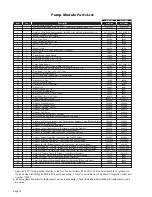
Page 18: ...0 JIC 37 Male 2 26579 21 1 Hose Assembly 1 8 Opposite Pump Side 16004A 086 22 1 Hose Assembly 1 8 Pump Side 16004A 046 23 2 Elbow 90 7 16 20 SAE O Ring Male 7 16 20 JIC 37 Male Orifice 26667 24 2 Cyli...

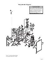
Page 19: ...ulic Pump Manual Backup Pump 23 21 22 18 10 12 2 23 24 24 20 19 19 15 16 17 13 17 28 11 25 17 8 5 5 Roll Stop Cylinder 27 26 25 14 1 34 4 3 33 29 Hydraulic Repair For repair of a hydraulic hose or cyl...

Page 20: ...s Fold Relay 32967A 32967A 38 1 Harness Light Relay 33362A 33362A 39 1 Wire Assembly Lift Interlock Connection 31797A 31797A 40 1 Wire Assembly Lift Stowed Connection tSee note below 31798A 31798A 41...

Page 21: ...bolts when retrofitting an M268 pump assembly Loctite is available from The Braun Corporation under part number 11522 1 12 11 21 14 31 17 26 14 23 35 4 29 25 13 13 20 41 16 44 39 40 14 15 15 5 18 34...

Page 22: ...5 16 18 X 3 4 BHSC AUTO BK 13 12 11 10 16 15 14 17 27208RW 1 WMT LATCH LIFT TITE REAR RETRO CABLE TIE 11 SOLID 10091 4 4 26614 2 13617 2 15328 4 24570 3 29729 2 31816 O RING 5 16 ID X 1 16 NUT 3 8 16...

Page 23: ...8 1 4 20 SS W PC DWG NOTES 1 LOOP TAPESWITCH WIRE BACK AND SECURE WITH WIRE TIE 4X 2 TRIM AND TUCK WIRE TIE CLASP INTO HOLE 4X DETAIL A SCALE 4X NOTE NOTE CLAMP INSULATED 1 3 8 WASHER 10 FLAT AUTO BK...

Page 24: ...UNC HEX LOCK AUTO BK WASHER 516ID X 1OD X 0269 AUTO BK RING 5 16 EXT SNAP ZINC PLATED BOLT 3 8 16 X 1 2 W NYLOCK PATCH BOLT SHOULDER 5 16 X 5 8 1 4 20 SS W PC DWG NOTES 1 LOOP TAPESWITCH WIRE BACK AND...

Page 25: ...ID X 1 16 NUT 3 8 16 UNC HEX LOCK AUTO BK WASHER 516ID X 1OD X 0269 AUTO BK RING 5 16 EXT SNAP ZINC PLATED BOLT 3 8 16 X 1 2 W NYLOCK PATCH BOLT SHOULDER 5 16 X 5 8 1 4 20 SS W PC DWG NOTES 1 LOOP TAP...

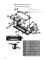
Page 26: ...12 1 16368 WASHER 5 16 EXTERNAL TOOTH 1 15858BK BOLT CARR 5 16 18 X 3 4 AUTO BK 13 1 10068 WASHER 5 16 LOCK AUTO BK 14 1 10058 NUT 5 16 18 HEX AUTO BK 2 4 5 3 10 7 1 11 12 8 9 14 13 6 DESCRIPTION 240...

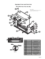
Page 27: ...3 QTY ITEM 1 PART NO 945 0412NA 1 2 BEARING FLANGE 3 4 X 3 8 12FDU06 4 24011 SHIM WASHER 906 ID X 1 156 OD 03 T SS 3 31771 4 1 2 3 5 4 SHIM WASHER 906 ID X 1 156 OD 03 T SS 31771 4 ARM PARALLEL BOTTOM...

Page 28: ...43 771 29 146 CYLINDER 14 625 29 146 RETRACTED ELBOW 1 4 NPT 90 1 4 BARB ELBOW 7 16 20 M O RNG 37 035 ORFICE DESCRIPTION 15150 26667 C1514 3 0408N PART NO 3 2 1 ITEM 1 1 1 QTY 30 10 Exploded Views an...

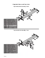
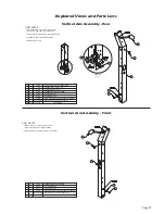
Page 29: ...m Assembly Rear Vertical Arm Assembly Front C2 2 5 3 4 7 6 1 8 NOTE 84383 32734 31062A 945 0448RNW PART NO 3 1 2 1 1 1 QTY ITEM 5 4 1 1 ROLLER LIFT TITE DESCRIPTION ASSY LIGHT VERT CHANNEL PHILIPS SOC...

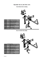
Page 30: ...ALE THREAD 12608 CLIP SAFETY GAS SPRING 1 32519A SWITCH ASSEMBLY INDICATES ITEMS NOT SHOWN Exploded Views and Parts Lists Front Handrail Assembly Rear Handrail Assembly 6 8 10 2 12 11 1 3 4 10 5 6 5 4...

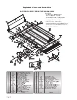
Page 31: ...30236R048 5 30236R032 5 947 3343NA 22 21 28 27 26 25 23 1 1 1 1 31 30 29 2 1 1 BUMPER RUBBER RECES 31 32 OD SPRING 1 4 X 1 EXT W HOOKS AUTO BK RIV POP SD64BS 3 16 13 25 AUTO BK ASSY LATCH ROLL STOP S...

Page 32: ...LOCK AUTO BK BOLT 5 16 18 X 1 1 4 LHSHCS AUTO BK PIN PLATFORM CYLINDER WASHER THRUST 875 OD 50 ID 0585T ADAPTER CYL ROLL STOP LEVER ROLL STOP ALUM RUBBER END ASSY 34 YEL CYLINDER FLAP ASSY 32949 947 0...

Page 33: ...Over 300 Braun Dealers Worldwide Providing Access to the World Providing Access to the World International Corporate Hdqrs P O Box 310 Winamac IN 46996 USA 1 800 THE LIFT 574 946 6153 FAX 574 946 4670...

Page 34: ...96 USA 1 800 THE LIFT 574 946 6153 FAX 574 946 4670 Braun Millennium 2 Series Braun Millennium 2 Series The Braun Corporation of Winamac Indiana warrants that it will repair or replace at Braun s sole...

Reviews: