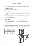
Page 15
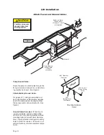
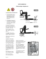
Lift Installation
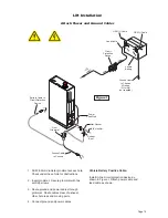
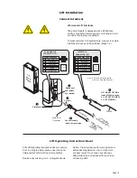
Connect Interlocks
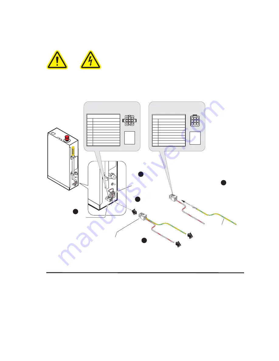
Vehicle and Lift Interlocks
The pump module is equipped with a lift interface
9-circuit connector (female socket). A mating 9-circuit
connector (male plug) is supplied.
To meet minimum CE requirements, connect to vehicle
interlock harness as outlined below (Steps 1-5).
INTERLOCK
CONNECTOR - P21
6
5
4
3
2
1
SIGNAL DEFINITION
NO.
9-COND WIRE CODE
7
8
9
VEHICLE SECURE (+12V INPUT)
LIFT NOT STOWED (GND)
NOT AVAILABLE
NOT AVAILABLE
NOT AVAILABLE
NOT AVAILABLE
NOT USED
NOT USED
LIFT STOWED (GND)
4
6 5
1
3 2
7
9 8
1
3
2
4
6
5
7
9
8
To Interlock
Disconnect
2
1
5
Disconnect
and remove
eye terminal
Connect
4
Connect vehicle
interlock signal wires
3
LIFT SIGNAL OPTIONS
Install 32638A in cavity:
5 (- LIFT NOT STOWED)
9 (- LIFT STOWED)
VEHICLE SECURE
SIGNAL
(Grey/Red)
LIFT SIGNAL
(Yellow/Light Blue)
PUMP MODULE
CONNECTOR - J21
6
5
4
3
2
1
SIGNAL DEFINITION
NO.
9-COND WIRE CODE
7
VEHICLE SECURE (+12V INPUT)
LIFT NOT STOWED (GND)
NOT AVAILABLE
NOT AVAILABLE
NOT AVAILABLE
NOT AVAILABLE
NOT USED
6
4 5
3
1 2
9
7 8
3
1
2
6
4
5
9
7
8
8
NOT USED
LIFT STOWED (GND)
9
Lift
Pump
Module
Note: Pins 5 and 9 are 3 Amp Max.
Pin 6 is 10 Amp Min. Supplied
Male 9-Pin
Connector
32638A
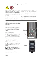
Lift Operating Instructions Decal
$IÀ[/LIW2SHUDWLQJ,QVWUXFWLRQVGHFDOWRYHKLFOH
door in a highly visible location near the hand-
held pendant control (lift operator position).
Replace any missing, worn, or illegible decals.
Notice: Clean surfaces with isopropyl alcohol
before decal application. Use a clean cloth
or paper towel. Do not use oily shop rags.
Wipe surface free of residue with dry portion
of cleaning cloth.
36513
Summary of Contents for Century 2 CLXT
Page 42: ...Page 40...

