Page 18
Lift Installation
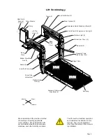
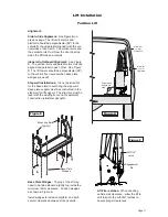
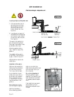
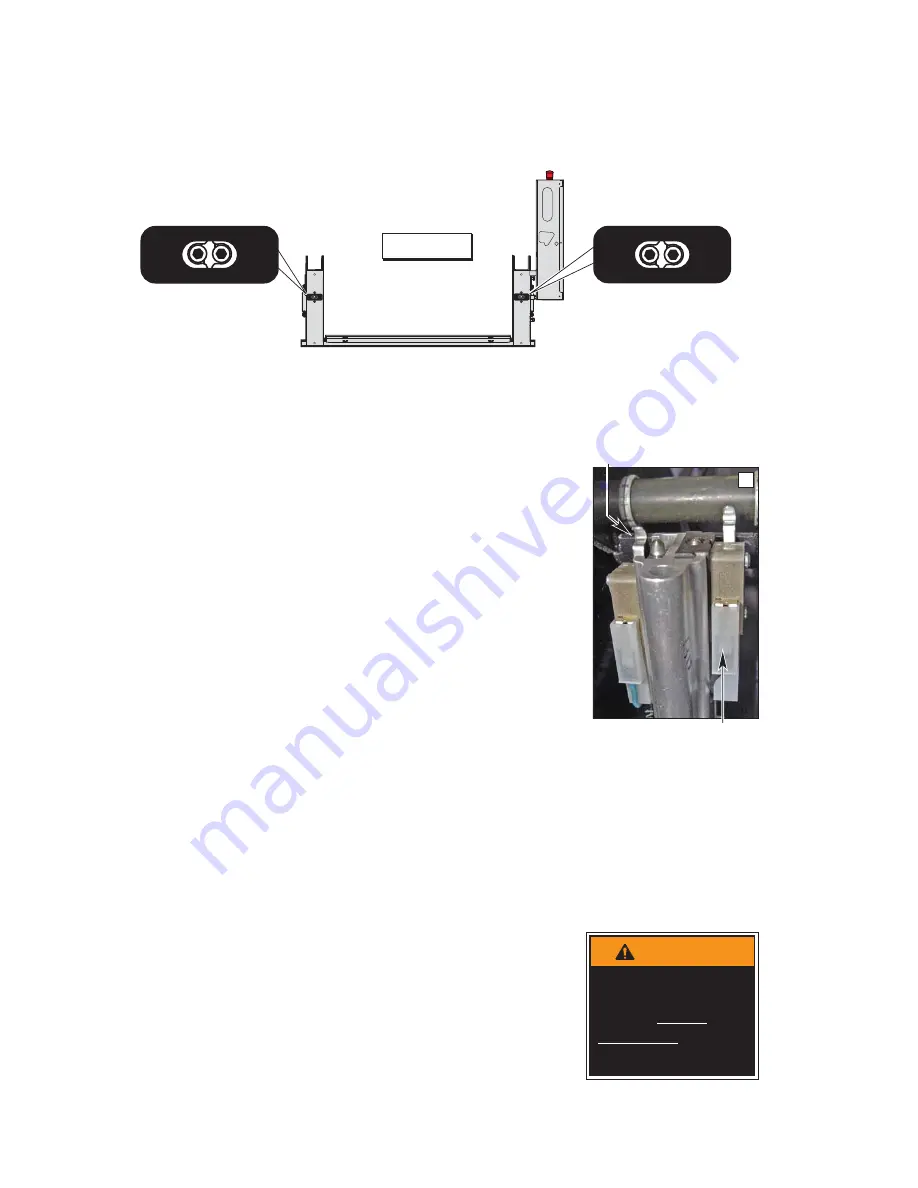
Tower Microswitch Adjustment
Review adjustment
procedures below and
adjust as needed only.
Left (rear) pump lift depicted.
Right (front) pump lift is a
mirrored image.
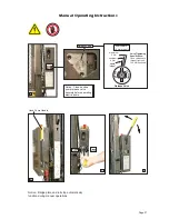
Tower 3 (Count) Switch Adjustment
Cycle Counter Switch
1. Position platform approximately 25 mm below
ÁRRUOHYHOSRVLWLRQXVLQJWKHSHQGDQWFRQWURO
2. View the Tower 3 microswitch inside the lift
tower (see Photo H). Turn switch adjustment
screw counterclockwise until microswitch no
longer contacts the activation plate.
3. Observe the cycle count number on the LCD
display. Slowly turn switch adjustment screw
clockwise until the microswitch activates
(clicks) and the number on the cycle counter
LCD has changed.
Tower 4 (Fold) Switch Adjustment
Partial Fold
3RVLWLRQSODWIRUPDWÝDQJOHXVLQJWKHPDQXDO
hand pump or pendant control.
2. View the Tower 4 microswitch inside the lift
tower (see Photo H). Turn the switch adjust-
ment screw in or out as needed until the radius
of the microswitch blade rides on the apex of
the activation plate.
3. Verify proper adjustment. Criteria below must
be met.
Proper Adjustment Criteria:
$SSO\SUHVVXUHSXVKGRZQRQRXWERDUGHQG
of platform by pressing the hand pendant
FOLD switch. The platform should not fold
(stow) with light pressure applied.
:KHQIROGLQJIXOO\WKHSODWIRUPVKRXOGVWRZ
tightly (snug with stow blocks).
TOWER
2
TOWER
1
32942
TOWER
4
TOWER
3
32943
Figure E
TOWER
2
TOWER
1
32942
TOWER
4
TOWER
3
32943
Improper microswitch
adjustment may
result in serious
bodily injury and/or
property damage.
WARNING
Radius of Tower 4 microswitch
blade activated by apex of
activation plate.
Tower 3 Microswitch
Platform Angle Adjustment:
Check platform angle after
Tower Microswitch Adjust-
ment procedures.
Platform Stop Blocks:
En-
sure both stop blocks are
making full contact with the
vertical arms.
H
Summary of Contents for Century 2 CLXT
Page 42: ...Page 40...

