background image

Page 39

NOTES

This page intentionally left blank.

Summary of Contents for Century 2 NCL Series

Page 1: ...MVSS No 403 This lift may be installed on all vehicles appropriate for the size and weight of the lift but must be installed on buses school buses and multi purpose passenger vehicles other than motor homes with a gross vehicle weight rating GVWR that exceeds 4 536 kg 10 000 lb DOT Public Use Lift www braunability com 631 West 11th Street Winamac IN 46996 USA Phone 1 574 946 6153 Fax 1 574 946 467...

Page 2: ...o Rev Date of Manufacture BraunAbility INDIANA USA BRAUNABILITY COM REV XXXXXXX SERIAL NUMBER XXXX Use Lift Max Lifting Capacity XXX lb XXXXXXX MODEL NUMBER MFG DATE XXXXXXX X Two BraunAbility Serial No identification tags shown below are posted on the lift One I D tag is posted on the opposite pump side vertical arm A second I D tag is located on the opposite pump side tower I D tags have the pro...

Page 3: ...11 14 Lift Electrical Schematic 15 Lift Wiring Diagram 16 Hydraulics Hydraulic Schematic 17 Hydraulics Parts List 18 Hydraulics Diagram 19 Repair Parts Pump Module Pump Module Parts List 20 Pump Module Diagram 21 Lift Exploded Views and Parts Lists Base Plate Assembly 22 25 Top Parallel Arm Assembly 26 Bottom Parallel Arm Assembly 27 Hydraulic Cylinder Assembly Main 28 Vertical Arm Assembly 29 Arm...

Page 4: ...p Side Vertical Arm Bottom Parallel Arms 2 Platform Lights 2 Front Inboard driver s side of vehicle Outboard Right Front Lift Tite Latches 2 Unfold Assist Compression Springs 2 Outer Barrier Activation Foot Outer Barrier Latches 2 Platform Side Plates 2 Platform Left Rear Inboard Towers 2 Threshold Warning Plate Audible Threshold Warning not visible Visual Threshold Warning Inner Roll Stop Lift Te...

Page 5: ...Switch 32519A Outer Barrier Occupied Raised Microswitch Rear 33775A Note Mirror image for right front pump lifts Outer Barrier Occupied Raised Microswitch Front 400374A IB Occupied Microswitch Stow Interlock Microswitch IB Occupied Stow Interlock Assy 403685AKS Bridging Microswitch 33689KS Threshold Alarm Microswitch Threshold Alarm Partial Fold Microswitch Assy 975 4121A Partial Fold Microswitch ...

Page 6: ...fold stow if occupied Refer to Platform Fold Pressure Adjustment procedures The inner roll stop will not raise if occupied The outer barrier will not raise if occupied Verify platform lighting when lift is deployed and pendant illumination when lift is powered A visual and audible warning will activate if the threshold area is occupied when the platform is greater than 1 below floor level 1 Verify...

Page 7: ...crew do not remove hex nut 4 Turn the adjustment screw counter clockwise until the platform does not fold when the Fold button is pressed 5 Turn the adjustment screw clockwise in 1 4 turn increments and press the Fold button until the platform folds completely Note Return the platform to floor level position after each attempt to fold the platform 6 Turn the adjustment screw an additional 1 8 turn...

Page 8: ... positioning as detailed in Tower Microswitch Adjustment Stop Block Vertical Arm Adjustment Screw Stop blocks must make full contact Heel Inboard Outboard Toe Rear Front Outboard passenger s side Inboard driver s side Arrows Direction of vehicle of vehicle Heel Ground Level Barrier must unfold fully Platform heel must lower fully Barrier Floor Level Wedges option Figure C 2 1 1 The outboard end to...

Page 9: ...cal arms D E Stop Block Guideline All Lift Models Right Wrong Turn clockwise to raise outboard end of platform When adjusting platform angle setting floor level position or adjusting bridging microswitch ensure both stop blocks are making full contact with the vertical arms Stop Block Vertical Arm Stop Block Vertical Arm Turn counter clockwise to lower outboard end of platform To raise the outboar...

Page 10: ...pump lift is a mirrored image Note Review adjustment procedures below and adjust as needed only Tower 1 Unfold Switch Adjustment Floor Position from Stow 1 Position platform at the fully stowed position using the manual hand pump or pendant control 2 Turn switch adjustment screw clock wise 3 full turns 3 Press pendant UNFOLD switch con tinue pressing switch until platform stops unfolding 4 When pl...

Page 11: ...Page 9 NOTES This page intentionally left blank ...

Page 12: ...ter Barrier Latch Roller Bearing 2 LO Outer Fold Arm Cam Followers 4 LO Outer Fold Arm Roller Pins 2 LO Hydraulic Cylinder Pivot Bushings 8 LO Inner Roll Stop Lever Bearings 2 and Slots 2 LO Outer Barrier Switch Lever Pivot Points 2 LO See the Maintenance Lubrication Schedule for recommended applications per number of cycles Outer Barrier Activation Foot Bearings 4 LO Inner Outer Fold Arm Contact ...

Page 13: ...t 750 cycle intervals fol lowing the scheduled 4500 cycle maintenance procedures These intervals are a general guideline for scheduling maintenance procedures and will vary according to lift use and conditions Lifts exposed to severe con ditions weather environment contamination heavy usage etc may require inspection and maintenance procedures to be performed more often than specified Cycle Counte...

Page 14: ... pivot bearings 2 Inner roll stop lever bearings 2 Inner roll stop lever slot 2 Saddle support bearings 8 Outer fold arm roller pins 2 Outer fold arm cam followers 4 Parallel arm pivot pin bearings 16 Handrail pivot pin bearings 4 Hydraulic cylinder pivot bushings 8 Inspect Lift Tite latch rollers for wear or damage positive securement and proper operation 2 Inspect inner roll stop for Wear or dam...

Page 15: ...r pivots 2 Outer barrier latch rollers 2 Outer fold arm cam followers 4 Outer fold arm roller pins 4 lock assy pins 4 Inner roll stop lever bracket pins 2 Inspect inner fold arm pins 2 bearings 8 and platform fold pins 2 for wear or damage and posi tive securement Remove pump module cover and inspect Hydraulic hoses fittings and connections for wear or leaks Harness cables wires terminals and conn...

Page 16: ...ere are no loose bolts broken welds or stress fractures Replace decals if worn missing or illegible Re place antiskid if worn or missing Maintenance and Lubrication Schedule continued Lift Disposal Procedure No lift components contain unacceptable amounts of lead cadmium mercury or hexavalent chromium 1 Lower platform to ground 2 Open pump module manual relief valve 3 Disconnect power from lift 4 ...

Page 17: ...8 GN 18 WH 18 GN 18 GN 18 BK 20 BK 20 DK BU 20 BK 16 CB1 RD 20 RD 18 RD 18 BK 18 RD 20 GN 20 RD 18 RD 18 RD 18 BU 18 BK 18 GN 18 WH 18 RD 18 WH 18 BK 18 BK 18 WH 18 WH 18 DK BU 18 WH 18 LT BU GN 18 GN 18 GN 20 WH 18 WH 18 GN 18 GN 18 WH 18 BK 18 RD 18 RD 18 OR 12 OR 12 OR 12 OR 12 OR 12 RD 18 RD 18 RD 18 BK 18 GN 18 GN 18 GN 18 RD 18 BK 20 BK 18 BK 18 BK 20 BK 20 GN 14 GN 18 GN 18 BK 22 RD 22 BK 2...

Page 18: ...N 18 BLACK 20 and BLACK 20 6 5 4 3 2 1 COLOR NO 7 COND WIRE CODE 7 2 1 5 4 3 7 6 C H COM NO NC Stow Interlock Microswitch BU 18 GN 18 BK 18 RD 18 WH 18 N O N C C H COM NO NC N O N C COM COM 33257ARP Lift Power Switch Down Fold Relief Up Fold Solenoid 87a 86 87 30 85 GN 20 LIFT STOWED NOT STOWED GROUND SIGNAL Located in cavity 5 or 9 see chart above 31798A YL LT BU 18 NOTES 1 JUNCTIONS ONLY OCCUR A...

Page 19: ...or Hydraulic Port M Orifice 1200 PSI Secondary Valve Folding Relief Valve Lifting Relief Valve Orifice Pump Side Cylinder BACKUP PUMP 2500 PSI Down Valve 1900 PSI PUMP Opposite Pump Cylinder Fixed Displacement Pump Vented Reservoir Backup Pump Single Acting Cylinder Check Valve Manual Shutoff Valve 2 Way 2 Position Solenoid Valve Pressure Compensated Flow Control Relief Valve Description Symbol De...

Page 20: ...Filler Screw On 30167 15 1 Fitting 90 1 8 NPT x 1 8 Barb Plastic 87563 16 1 Clamp Hose Solenoid Mounting 29663 17 2 Cap Barbed Fitting CAP10 3 18 1 Handle with Grip 17206A 19 1 Fitting Male 7 16 20 SAE O Ring to Male 7 16 20 JIC 37 24504 20 1 Elbow 7 16 20 JIC 37 Female Swivel 1 7 16 20 JIC 37 Male 2 26579 21 1 Hose Assembly 1 8 Opposite Pump Side 16004A 086 22 1 Hose Assembly 1 8 Pump Side 16004A...

Page 21: ... 9 12 20 19 16 13 17 3 10 Hydraulic Pump Motor 7 4 14 15 23 11 1 26 Hydraulic Repair For repair of a hydraulic hose or cylinder read this Service Bulletin 27049 2 25 Opposite Pump Side Cylinder 24 17 23 Pump Side Cylinder Hydraulics Diagram ...

Page 22: ... 403728 29 1 Cycle Counter LCD w o Reset 3See note below 30547 30547 30 1 Flasher 12V 32461 32461 31 2 Relay 30 40A SPDT 12V with Internal Diode 35249 35249 32 1 Diode Assembly Up Solenoid 3See note below 73906A 73906A 33 1 Cable Pump Module Power 3See note below 26082A 4 26082A 4 34 1 Harness Main 3See note below 404346A 404346A 35 1 Fitting Male 7 16 20 O Ring to Male 7 16 20 JIC 37 3See note be...

Page 23: ...8 25 24 27 3 17 1 24 18 18 UP DO WN 32819 FOL D UN FOL D 32820 32 20 2 Pump Mounting Bolts Apply Loctite Threadlocker Red 271 or equivalent to the three pump mount ing bolts items 25 if a blue nylon patch is not present on the bolts when retrofit ting an M268 pump assembly Note Left rear pump module shown right front pump module mirror image ...

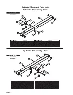
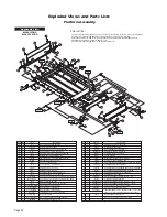
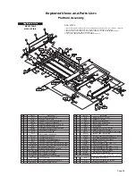
Page 24: ... 16 25 38 AUTO BK 14993 20 21 PIN PIVOT PARALLEL ARM 936 0403 4 1 36075KS KIT THRESHOLD TRANSITION RUBBER NOSE 23 22 4 4 WASHER 1 2 FLAT AUTO BK 25346 SCREW 5 16 18 X 3 4 FHS AUTO BK 25527 27208FWBM WMT LATCH LIFT TITE FRONT RETRO 27208RWBM WMT LATCH LIFT TITE REAR RETRO 2 11 2 28339BK NUT 3 8 16 TOP LOCK AUTO BK DWG NOTES 1 LOOP TAPESWITCH WIRE BACK AND SECURE WITH WIRE TIE 2X 2 TRIM AND TUCK WIR...

Page 25: ...2 2 CLAMP INSULATED 1 1 2 402530 RIV POP SD66BS 3 16 25 38 AUTO BK 14993 27208FWBM WMT LATCH LIFT TITE FRONT RETRO 27208RWBM WMT LATCH LIFT TITE REAR RETRO 2 17 NOTE 1 DETAIL A NOTE 1 NOTE 2 SCALE 4X DWG NOTES 1 LOOP TAPESWITCH WIRE BACK AND SECURE WITH WIRE TIE 2X 2 TRIM AND TUCK WIRE TIE CLASP INTO HOLE 4X 3 APPLY LOCTITE THREADLOCKER RED 271 OR EQUIVALENT TO ALL 25527 SCREWS 4 APPLY LOCTITE THR...

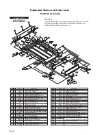
Page 26: ...T SHOULDER 5 16 X 5 8 1 4 20 SS W PC 19 2 RIV POP SD66BS 3 16 25 38 AUTO BK 14993 20 21 PIN PIVOT PARALLEL ARM 936 0403 4 1 36075KS KIT THRESHOLD TRANSITION RUBBER NOSE 23 22 4 4 WASHER 1 2 FLAT AUTO BK 25346 SCREW 5 16 18 X 3 4 FHS AUTO BK 25527 27208FWBM WMT LATCH LIFT TITE FRONT RETRO 27208RWBM WMT LATCH LIFT TITE REAR RETRO 2 A DWG NOTES 1 LOOP TAPESWITCH WIRE BACK AND SECURE WITH WIRE TIE 2X ...

Page 27: ...SD66BS 3 16 25 38 AUTO BK 14993 27208FWBM WMT LATCH LIFT TITE FRONT RETRO 27208RWBM WMT LATCH LIFT TITE REAR RETRO 2 17 NOTE 1 DETAIL A NOTE 1 NOTE 2 SCALE 4X 20 21 PIN PIVOT PARALLEL ARM 936 0403 4 1 36075KS KIT THRESHOLD TRANSITION RUBBER NOSE 23 22 4 4 WASHER 1 2 FLAT AUTO BK 25346 SCREW 5 16 18 X 3 4 FHS AUTO BK 25527 11 2 28339BK NUT 3 8 16 TOP LOCK AUTO BK A DWG NOTES 1 LOOP TAPESWITCH WIRE ...

Page 28: ...LE 1 2 PLASTIC 14 1 26362 RIVET SNAP BLACK 201 X 256 295 9 9 3 5 6 5 6 10 11 12 7 7 10 11 12 8 8 3 4 4 13 14 24011 4 2 1 1 945 4419FNAKS BEARING FLANGE 3 4 X 3 8 12FDU06 PARALLEL ARM ASSY TOP FRONT SHIP OUT KIT ITEMS 1 12 3 4 5 1 14993 RIV POP SD66BS 3 16 25 38 AUTO BK 1 915 0703BM BRACKET INNER SIDE PANEL GUIDE 6 1 24440 BOLT 5 16 18 X 3 4 BHSC AUTO BK 16368 WASHER 5 16 EXTERNAL TOOTH DESCRIPTION...

Page 29: ... SCREW 25527 AND TORQUE TO 225 IN LB 2 CONNECT IB OCC STOW HARNESS BEFORE INSTALLING SWITCH ASSEMBLY INTO PARALLEL ARM NOTE 1 NOTE 2 ITEMS 6 8 ARE MIRROR IMAGE WHEN ARM IS LOCATED ON FRONT SIDE OF LIFT ARM PARALLEL BOTTOM SHIP OUT KIT Incl Items 1 4 1 QTY ITEM 403962AKS 1 2 BEARING FLANGE 3 4 X 7 8 x 1 LONG 12FTH16 4 402469 1 2 3 4 5 NOTE 1 6 7 3 COVER PLATE BOTTOM PARALLEL ARM 4 403963BM 4 SCREW ...

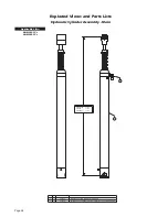
Page 30: ...nder Assembly Main RETRACTED EXTENDED STROKE 14 640 41 873 27 233 CYLINDER ASSY BOXED PARALLEL ARM 48 FTG INCLUDES ITEM 2 ELBOW 7 16 20 M O RNG 37 035 ORFICE 402043 402948 2 1 1 1 DESCRIPTION PART NO ITEM QTY 1 2 Applicable Lifts All NCL917 s All NCL919 s ...

Page 31: ...ITE ROLLER W BEARING 404417A 5 5 5 5 10 10 NOTE 3 NOTE 1 3 6 6 5 5 6 5 1 4 NOTE 2 11 11 11 10 9 8 7 2 10 Applicable Lifts Applicable Lifts All NCL917 s All NCL919 s All NCL917 s All NCL919 s PART NO QTY ITEM DESCRIPTION DWG NOTES 1 INSERT SOCKET OF LIGHT ASSY THRU TOP KEY WHILE INSTALLING LIGHT TIGHTEN SCREWS 2 APPLY LOCTITE THREADLOCKER RED 271 OR EQUIVALENT TO ALL 25527 SCREWS DWG NOTES 1 INSERT...

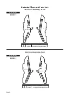
Page 32: ...LEL ARM OUTSIDE FRONT 4 1 1 1 945 0701NA COVER PLASTIC PARALLEL ARM INSIDE FRONT SMOOTH SIDE COVER PLASTIC PARALLEL ARM INSIDE REAR 945 0703NA 4 1 SMOOTH SIDE 3 COVER PLASTIC PARALLEL ARM OUTSIDE REAR 915 0702NA 3 1 SMOOTH SIDE SMOOTH SIDE 2 DESCRIPTION PART NO QTY ITEM 1 2 915 0704NA DESCRIPTION PART NO QTY ITEM COVER PLASTIC PARALLEL ARM OUTSIDE FRONT Exploded Views and Parts Lists Arm Cover Ass...

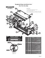
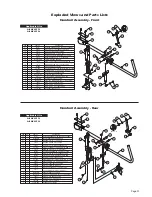
Page 33: ...3 8 16 x 1 2 FLBHSCS 6G8 PATCH 29942 1 23 CUP INBOARD BARRIER UP SWITCH LEVER 403300 1 16 21 1 21 23 3 4 6 7 8 12 9 11 10 5 6 8 10 7 11 1 3 4 9 5 13 14 15 4 17 16 QTY ITEM PART NO DESCRIPTION 20 16 18 15 19 13 2 18 17 12 2 14 4 7 6 5 4 3 1 1 945 0618NA HANDRAIL ASSY NHTSA 12 11 10 8 9 1 1 2 1 2 1 1 1 2 1 10027 BOLT 3 8 16 X 2 HEX HD CAP 18657 RING 3 4 EXT SNAP AUTO BK 900 0413N PIN PIVOT LOWER ARM...

Page 34: ...O BK 18 BRACKET ADJUST SPLIT FOOT 2 33411BM 20 2 36003 HAIRPIN COTTER STAINLESS 042 DECAL BOUNDARY YELLOW LEXAN 1 x 35 1 2 2 32 30236R035 5 DECAL BOUNDARY YELLOW LEXAN 1 x 32 1 2 1 33 30236R032 5 PIN ROLLSTOP GAS SPRING 2 34 401002 PART NO QTY ITEM DESCRIPTION DECAL BOUNDARY YELLOW LEXAN 1 X 11 2 35 30236R011 4 36 40 2900 0 SCREW 5 16 18 X 1 BHCS BEARING FLANGE 3 4 X 1 4 12FDU04 2 37 24012 BLOCK I...

Page 35: ...042 DECAL BOUNDARY YELLOW LEXAN 1 x 35 1 2 2 32 30236R035 5 DECAL BOUNDARY YELLOW LEXAN 1 x 32 1 2 1 33 30236R032 5 PIN ROLLSTOP GAS SPRING 2 34 401002 PART NO QTY ITEM DESCRIPTION DECAL BOUNDARY YELLOW LEXAN 1 X 11 2 35 30236R011 4 36 40 2900 0 SCREW 5 16 18 X 1 BHCS BEARING FLANGE 3 4 X 1 4 12FDU04 2 37 24012 BLOCK INBOARD BARRIER STOW BUMPER 2 38 403885 ASSEMBLY INBOARD BARRIER BRACKET W PIN RE...

Page 36: ...2 1 33 30236R033 5 PIN ROLLSTOP GAS SPRING 2 34 401002 PART NO QTY ITEM DESCRIPTION DECAL BOUNDARY YELLOW LEXAN 1 X 11 2 35 30236R011 4 36 40 2900 0 SCREW 5 16 18 X 1 BHCS BEARING FLANGE 3 4 X 1 4 12FDU04 2 37 24012 BLOCK INBOARD BARRIER STOW BUMPER 2 38 403885 ASSEMBLY INBOARD BARRIER BRACKET W PIN REAR 1 39 404412A BEARING UHMW FLAT THIN BLK 3 40 916 5406 ASSEMBLY INBOARD BARRIER BRACKET W PIN F...

Page 37: ... 32 30236R035 5 DECAL BOUNDARY YELLOW LEXAN 1 x 33 1 2 1 33 30236R033 5 PIN ROLLSTOP GAS SPRING 2 34 401002 PART NO QTY ITEM DESCRIPTION DECAL BOUNDARY YELLOW LEXAN 1 X 11 2 35 30236R011 4 36 40 2900 0 SCREW 5 16 18 X 1 BHCS BEARING FLANGE 3 4 X 1 4 12FDU04 2 37 24012 BLOCK INBOARD BARRIER STOW BUMPER 2 38 403885 ASSEMBLY INBOARD BARRIER BRACKET W PIN REAR 1 39 404412A BEARING UHMW FLAT THIN BLK 3...

Page 38: ...nd to exist during the fourth or fifth year of warranty coverage to the following lift s power train parts Cable Cylinder Flow Control Gear Box Motor Pump Hydraulic Hose and Fittings it will be repaired or replaced at Braun s option without charge to the owner for parts only in accordance with the terms conditions and limitations of this limited warranty The cost of labor for repair or replacement...

Page 39: ...tted by law notify Braun directly in writing at the above address of the unsuccessful repair s of the alleged defect s so that Braun can become directly involved in providing service pursuant to the terms of this limited warranty WHAT IS NOT COVERED This Limited Warranty does not cover any of the following defects in materials components or parts of the product not attributable to Braun any materi...

Page 40: ...any action of Braun or any agent of Braun shall be interpreted as an extension of any warranty period or the filing limitation period in this paragraph Some states do not allow a reduction in the statute of limitations so this reduction may not apply to you WARRANTY REGISTRATION and MISCELLANEOUS Your warranty registration records should be completed and delivered to the appropriate companies incl...

Page 41: ...Page 39 NOTES This page intentionally left blank ...

Page 42: ... buses and multi purpose passenger vehicles other than motor homes with a gross vehicle weight rating GVWR that exceeds 4 536 kg 10 000 lb DOT Public Use Lift www braunability com 631 West 11th Street Winamac IN 46996 USA Phone 1 574 946 6153 Fax 1 574 946 4670 Service Manual Manufacturing Revision Level Rev I Century 2 NCL All illustrations descriptions and specifications in this document are bas...

Reviews: