background image

Fi

t a

n

d u

se

12

13

Retractable tie-downs

Retractable tie-downs

1.

The Solo floor anchors will have been installed in the vehicle in accordance

with their own and the vehicle converter’s instruction. Position the wheelchair

within the vehicle as required.

2.

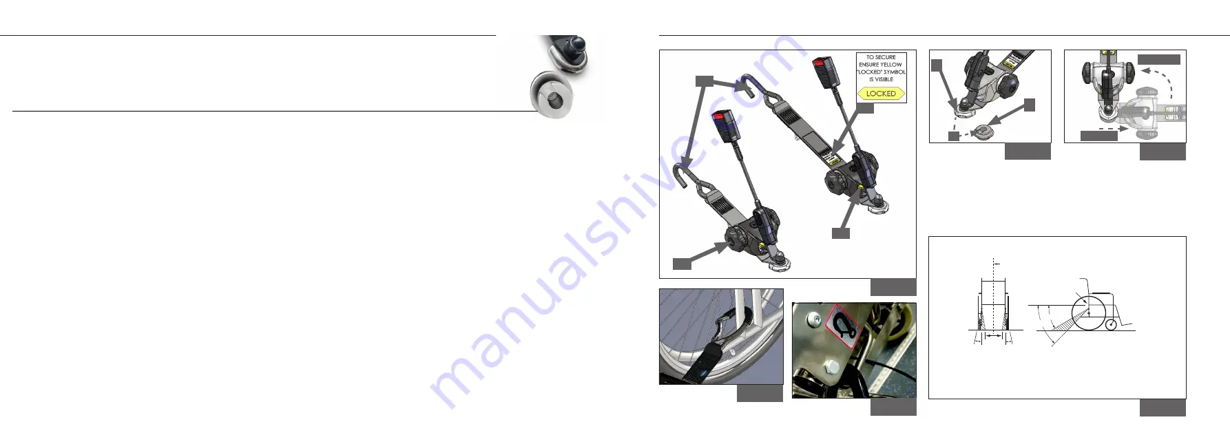
Install each front retractor cleat onto a front Solo anchor by aligning the open

mouth of the cleat and the protrusion, (Fig. 6C), to the slot on the floor anchor.

Slide the cleat fully home (allowing the keyway within the cleat to guide into

its home position, Fig. 6A & B) and rotate the cleat through 90° to align the

retractor with the wheelchair frame, (Fig. 7).

3.

Dependent on retractor type, follow instruction:

Quattro: Press the release button(s), (Fig. 5B), to release the webbing and

attach each J-hook arrangements to the wheelchair’s rear frame, with the

open gate facing outboard. (Some wheelchairs will indicate this position, Fig.

3). Press the yellow button(s) again to remove the webbing slack.

Quattro Express:

 Webbing can be extended from the reel without pressing

the yellow button if the lock label, (Fig. 5D), is NOT visible. Attach each of the

wheelchair attachments to the wheelchair’s rear frame. (Some wheelchairs

will indicate this position, Fig. 3). The yellow button must be pressed if

extending webbing with the label in view, (Fig. 5B). The webbing will retract

automatically into the reel. 

IMPORTANT: The yellow locking label must be

fully visible to ensure that the reel is locked off, (Fig. 5D).

4.

Final tensioning is achieved by turning each tensioning handle, (Fig. 5B), until

the webbing is equally taut on each side.

5.

Ensure that the webbing of each tie-down is approximately the same length,

and at an angle of around 30 to 45°, within the rear view zone, (Fig. 8).

6.

The occupant restraint must now be fitted. Please refer to relevant manual.

Removing the combined retractable 

tie-downs

IMPORTANT: First remove the 

occupant restraint.

1.

Release the tension in the front

tie-downs by pressing the yellow

button, (Fig. 5B), and extending

the webbing to allow the J-hook,

(Fig. 5A), to be removed from the

wheelchair frame. If the webbing

is particularly tight, it may be

necessary to slightly ’tension’ the

webbing with the hand wheel,

(Fig 5C), while pressing the yellow

button, (Fig. 5B), to remove the

webbing lock on the retractor.

2.

Remove each front retractor from

the anchor by rotating the tie-

down through 90° so that the

raised protrusion, (Fig. 6C), on the

cleat is facing its parallel cleat.

3.

Pull the tie-down away from the

floor anchor and store safely.

Fit and use

C

lassic

 retractable tie-downs

Solo anchor - reversible stalk (I- products) - rear

Figure 7

- slide on

- rotate 90°

D

Figure 5

A

B

C

Figure 4

Figure 8

Rear

securement

points

Wheelchair

reference

plane

45°

30°

SIDE VIEW

REAR VIEW

10°

10°

300mm

(12in)

NOTE Note that angles indicated are obtained by projecting the angle of each tie-down strap 

onto a vertical plane parallel to the wheelchair reference plane (side view) or onto a vertical 

plane that is perpendicular to the wheelchair reference plane (rear view).

Figure 3

Figure 6

C

B

A

Summary of Contents for I-RQ10MJ

Page 1: ...and use Applicable to products I RQE10MK I RQ10MT I RQ10PT I RQE10MH I RQ10PJ I RQ10MJ I RQE10PJ I RQE10MJ I SQE10PK I SQ10MJ I SQE10PJ I SQE10MJ K RQE10MK K RQ10MT K RQ10PH K RQE10MH K RQ10PJ K RQ10...

Page 2: ...ompact wheelchair tie downs Index Declaration of conformity at the end of the manual Thank you for choosing Classic wheelchair tie downs from BraunAbility The following manual is an important part of...

Page 3: ...ompact wheelchair tie downs Index Declaration of conformity at the end of the manual Thank you for choosing Classic wheelchair tie downs from BraunAbility The following manual is an important part of...

Page 4: ...uous process Applications are added on a regular basis For more details contact BraunAbility or look on the BraunAbility website I RQ10MT I SQE10PJ K RQE10MK K SQ10PJ Safety information 4 5 Compact wh...

Page 5: ...uous process Applications are added on a regular basis For more details contact BraunAbility or look on the BraunAbility website I RQ10MT I SQE10PJ K RQE10MK K SQ10PJ Safety information 4 5 Compact wh...

Page 6: ...nd the equipment should be used only if all components are in good condition Warning protect webbing from contacting sharp edges and corners Replace equipment if the webbing becomes cut frayed or cont...

Page 7: ...nd the equipment should be used only if all components are in good condition Warning protect webbing from contacting sharp edges and corners Replace equipment if the webbing becomes cut frayed or cont...

Page 8: ...ssenger There should also be 200mm 8in of clear space either side of the wheelchair center line If these clear space dimensions cannot be provided then any structure protruding into this area should b...

Page 9: ...ssenger There should also be 200mm 8in of clear space either side of the wheelchair center line If these clear space dimensions cannot be provided then any structure protruding into this area should b...

Page 10: ...OT visible Attach each of the wheelchair attachments to the wheelchair s rear frame Some wheelchairs will indicate this position Fig 3 The yellow button must be pressed if extending webbing with the l...

Page 11: ...OT visible Attach each of the wheelchair attachments to the wheelchair s rear frame Some wheelchairs will indicate this position Fig 3 The yellow button must be pressed if extending webbing with the l...

Page 12: ...at the reel is locked off Fig 5D 4 Final tensioning is achieved by turning each tensioning handle Fig 5B until the webbing is equally taut on each side 5 Ensure that the webbing of each tie down is ap...

Page 13: ...at the reel is locked off Fig 5D 4 Final tensioning is achieved by turning each tensioning handle Fig 5B until the webbing is equally taut on each side 5 Ensure that the webbing of each tie down is ap...

Page 14: ...T visible Attach each of the wheelchair attachments to the wheelchair s rear frame Some wheelchairs will indicate this position Fig 3 The yellow button must be pressed if extending webbing with the la...

Page 15: ...T visible Attach each of the wheelchair attachments to the wheelchair s rear frame Some wheelchairs will indicate this position Fig 3 The yellow button must be pressed if extending webbing with the la...

Page 16: ...Webbing can be extended from the reel without pressing the yellow button if the lock label Fig 10D is NOT visible Attach each of the wheelchair attachments to the wheelchair s rear frame Some wheelcha...

Page 17: ...Webbing can be extended from the reel without pressing the yellow button if the lock label Fig 10D is NOT visible Attach each of the wheelchair attachments to the wheelchair s rear frame Some wheelcha...

Page 18: ...re that it cannot become a projectile in an accident Regularly inspect the wheelchair restraint systems for damage wear or malfunction If any problems are identified replace components immediately Whe...

Page 19: ...MJ K SQE10PK K SQ10PJ K SQ10MJ K SQE10PJ K SQE10PJ Accredited by URS as testing laboratory in accordance with ISO IEC 17025 2005 Quality system certified in accordance with ISO 9001 2008 Illustrations...

Page 20: ...re that it cannot become a projectile in an accident Regularly inspect the wheelchair restraint systems for damage wear or malfunction If any problems are identified replace components immediately Whe...

Page 21: ...MJ K SQE10PK K SQ10PJ K SQ10MJ K SQE10PJ K SQE10PJ Accredited by URS as testing laboratory in accordance with ISO IEC 17025 2005 Quality system certified in accordance with ISO 9001 2008 Illustrations...

Page 22: ...UI12356 BraunAbility UK Ltd Unwin House The Horseshoe Coat Road Martock Somerset TA12 6EY UK Toll Free 800 488 0359 Email questions braunability com www braunability eu...

Reviews: