Page 15
Page 14
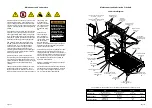
DOOR OPENING
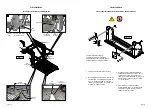
Lift Base Plate
NEG.
POS.
Pump
Module
Battery
Chassis
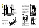
Figure J
Battery to Frame
Ground Cable
4 Gauge (21.1mm2)
(not supplied)
Pump Mounted
Ground Cable
4 Gauge
(21.1mm2)
Grommet
Pump
Module
Chassis
Chassi
s
5/16”
External Tooth
Star Washer
5/16-18 x 3/4”
Thread Cutting
Screw
9/32” Diameter
Pilot Hole
Pump Ground Cable:
Route the pump mounted cable through the
floor grommet and connect to a vehicle fram
-
ing member as shown. See Figure J.
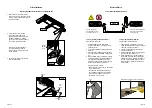
Vehicle Battery Ground Cable:
A 4 gauge (21.1mm2) ground cable must
be connected from vehicle battery negative
post to the same vehicle framing member
the pump ground cable is attached to. See
Figure J.
Ground Cable Corrosion:
When mount-
ing ground cables, remove undercoating,
dirt, rust, etc. from framing member around
mounting holes (minimum 16mm diameter
area). Apply protective coating to mounting
holes to prevent corrosion. Failure to do so
will void warranty of certain electrical compo-
nents.
Position and secure
ground cable clear
of lift operation.
CAUTION
CAUTION
CAUTION
CAUTION
Lift Installation
Attach Power and Ground Cables
Lift Installation
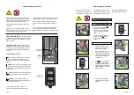
Connect Interlocks
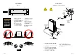
Vehicle and Lift Interlocks
The pump module is equipped with a lift interface
9-circuit connector (female socket). A mating 9-circuit
connector (male plug) is supplied.
To meet minimum CE requirements, connect to vehicle
interlock harness as outlined below (Steps 1-5).
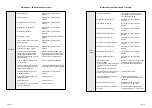
INTERLOCK
CONNECTOR - P21
6
5
4
3
2
1
SIGNAL DEFINITION
NO.
9-COND WIRE CODE
7
8
9
VEHICLE SECURE (+12V INPUT)
LIFT NOT STOWED (GND)
NOT AVAILABLE
NOT AVAILABLE
NOT AVAILABLE
NOT AVAILABLE
NOT USED
NOT USED
LIFT STOWED (GND)
4
6 5
1
3 2
7
9 8
1
3
2
4
6
5
7
9
8
To Interlock
Disconnect
2
1
5
Disconnect
and remove
eye terminal
Connect
4
Connect vehicle
interlock signal wires
3
LIFT SIGNAL OPTIONS
Install 32638A in cavity:
5 (- LIFT NOT STOWED)
9 (- LIFT STOWED)
VEHICLE SECURE
SIGNAL
(Grey/Red)
LIFT SIGNAL
(Yellow/Light Blue)
PUMP MODULE
CONNECTOR - J21
6
5
4
3
2
1
SIGNAL DEFINITION
NO.
9-COND WIRE CODE
7
VEHICLE SECURE (+12V INPUT)
LIFT NOT STOWED (GND)
NOT AVAILABLE
NOT AVAILABLE
NOT AVAILABLE
NOT AVAILABLE
NOT USED
6
4 5
3
1 2
9
7 8
3
1
2
6
4
5
9
7
8
8
NOT USED
LIFT STOWED (GND)
9
Lift
Pump
Module
Note: Pins 5 and 9 are 3 Amp Max.
Pin 6 is 10 Amp Min. Supplied
Male 9-Pin
Connector
Mounting Hardware
Detail
32638A
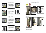
Lift Operating Instructions Decal
Affix Lift Operating Instructions decal to vehicle
door in a highly visible location near the hand-
held pendant control (lift operator position).
Replace any missing, worn, or illegible decals.
Notice: Clean surfaces with isopropyl alcohol
before decal application. Use a clean cloth
or paper towel. Do not use oily shop rags.
Wipe surface free of residue with dry portion
of cleaning cloth.
36513


