11
Fault messages
Fault Message
Fault Log Entry
Explanation
Probable Cause
Possible Remedy
Pressure Measurement
fault
"Press.Meas.Flt"
Loss of pressure signal
Pressure transducer pipe
disconnected.
Pressure transducer fault.
Reconnect pipe and restart
machine.
Replace power board.
Technical Fault
Vent Now in Safe Mode
Stop Using This Machine
Note 1
Safe Mode
Ventilator has set to minimum output
following a pressure measurement fault.
This prevents operation with no feedback.
Pressure transducer pipe
disconnected.
Pressure transducer fault.
Reconnect pipe and restart
machine.
Replace power board.
Blower Control fault
"Blower Flt."
Blower controller fault or blower stopped.
Seized Blower motor
Controller fault
Replace blower
Replace power board.
Blower speed fault
"Blower Spd.Flt."
Error between blower speed command
and actual blower speed.
Motor fault
Controller fault
Replace blower
Replace controller
Enclosure Temperature
fault
"Box Ov/Un
Tmp."
Internal temperature below 5 degrees or
above 60 degrees.
Machine covered, operated
in high ambient temperature
or cooling vents blocked.
Check operational
environment.
Check cooling fan operation
and vents.
Power supply fault
"Main Power Flt"
Internal power supply voltage out of spec.
Less than 22 volts or greater than 26 volts.
Power supply fault
Replace power supply
Control System fault
"Int.Coms.Flt."
Communication failure between internal
micros.
Failure of command micro
or power micro.
Replace command board or
power board.
Note 1: The technical fault message informs the user that the ventilator has switched to safe mode to protect against operation
without pressure feedback. The output is sufficient to clear exhaled gas only. If the original fault (pressure measurement fault) is still
present, this message will alternate with the pressure measurement fault message with each press of Mute. If the original fault has
cleared, only the technical fault message will be shown. Mute time in this configuration is reduced to 10 seconds. The pressure
measurement fault should be investigated.
Summary of Contents for Nippy 3+
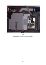
Page 18: ...16 Fig 3 Inside the base with the control board removed...
Page 32: ...30...
Page 33: ...31 Circuit Diagrams...
Page 34: ...32...
Page 35: ...33 0901 0901 PCB assembly for Control Board primary side 16 11 07...
Page 36: ...34 0901 0901 PCB assembly for Control Board secondary side 16 11 07...
Page 37: ...35 0756 C 17 02 04 A4 1 1 Component Layout for Nippy 3 Command Board 0756 C...
Page 38: ...36...
Page 39: ...37...
Page 40: ...38...
Page 41: ...39...
Page 42: ...40...
Page 43: ...41...
Page 44: ...42 4 7 0 0 u F...


