17
1
2
3
4
5
6
7
8
9
10
Fig 4.
Inside the Lid
1. RS 232 Port
2. Board to Board Ribbon
Connector
3. Memory Battery Switch
4. Display Connector
5. Display Back-light Connector
(Input)
6. Keypad Connector
7. Alarm Sounder
8. Display Back-light Connector
(Output)
9. Second Alarm Sounder
10. Alarm and Memory Back-up
Battery
Summary of Contents for Nippy 3+
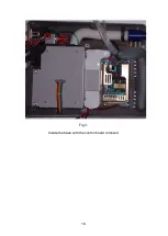
Page 18: ...16 Fig 3 Inside the base with the control board removed...
Page 32: ...30...
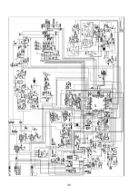
Page 33: ...31 Circuit Diagrams...
Page 34: ...32...
Page 35: ...33 0901 0901 PCB assembly for Control Board primary side 16 11 07...
Page 36: ...34 0901 0901 PCB assembly for Control Board secondary side 16 11 07...
Page 37: ...35 0756 C 17 02 04 A4 1 1 Component Layout for Nippy 3 Command Board 0756 C...
Page 38: ...36...
Page 39: ...37...
Page 40: ...38...
Page 41: ...39...
Page 42: ...40...
Page 43: ...41...
Page 44: ...42 4 7 0 0 u F...

